A Week in and out the Shop
Published 19 Sep 2022
Tags: 3d printing, älgen, delfinen, ferrules, fusion 360, jigs, laser-cutting, patching, templates
Älgen
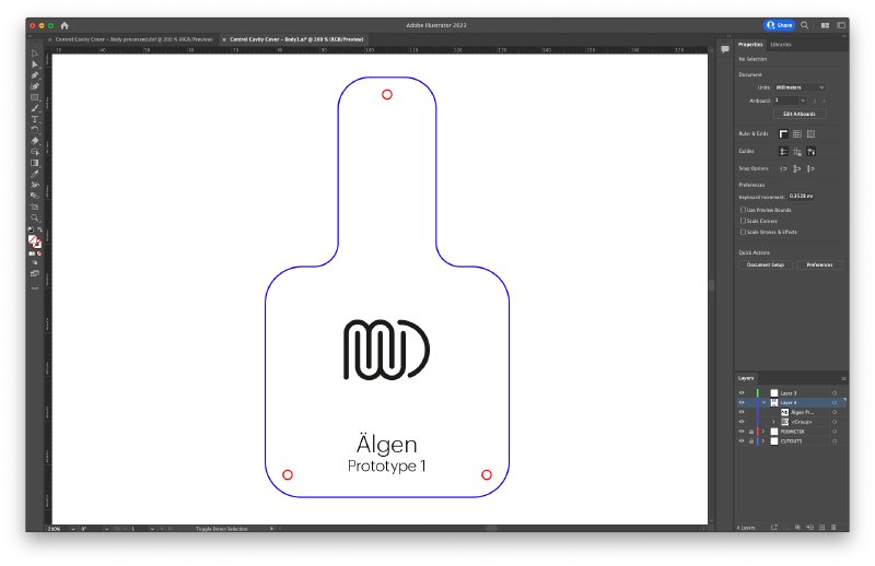
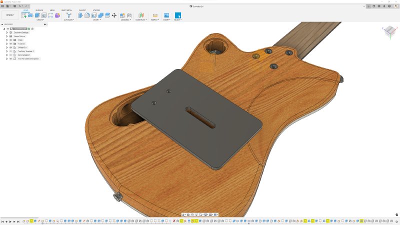
In last week’s post I wrapped up by making the design for the electronics cavity cover for Älgen, which looked like this:
In the past I’ve made the covers like this using wood, but given the mixed-media nature of Älgen I wanted to go with a fancy acrylic. Back when I started doing laser-cutting, the laser-safe acrylic you could readily get hold off was either a primary colour or back or white, but since then I know that the state of laser safe acrylic has moved on a lot: you want confetti glitter acrylic? you got it! You want disco orange? you got it! You want marble/pearloid/totroiseshell effect? you got it!. It was really exciting to see all the options out there now that I could potentially use in builds. In the end I tried to not get carried away, and bought a modest selection for use on both Älgen and the Delfin build.
For the control cover on Älgen I went with some smoked translucent brown acrylic that shouldn’t distract too much from the walnut wood on Älgen, but will let you see a hint of the electronics within. So off I went into Makespace to do some laser cutting:
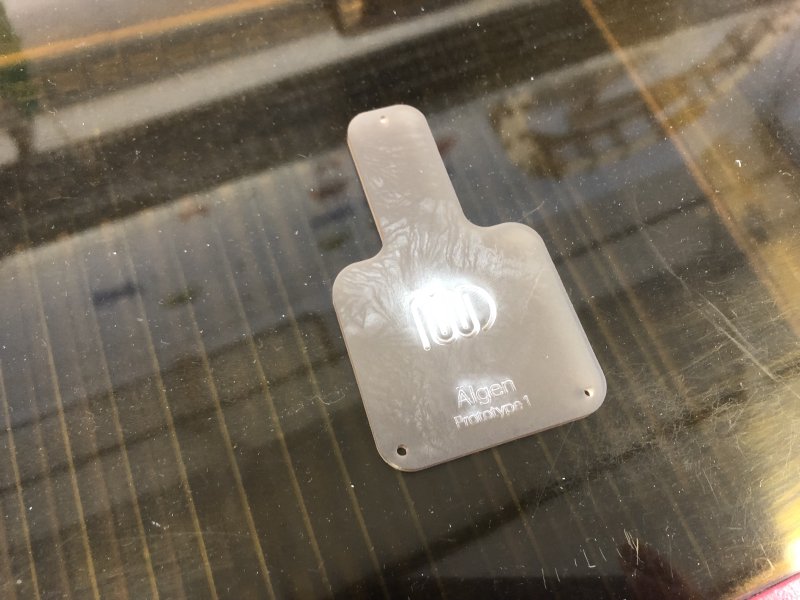
Not a great picture, but it was seven in the morning when I did this, so great photography wasn’t on my mind :) It looks ruined, but that’s just over-exposure of where the vapour from the etching has condenced as a white residue on the plastic. Annoyingly I had taken the protective film off to see the acrylic when I got it, which means that all vapour from the etched area was left on the top and I had to clean it up later. Thankfully some dish-washing liquid and a non abrasive cloth got rid of most of it, and before I invested the time in fully cleaning it, I discovered it wasn’t fit for purpose, alas.
Unfortunately, I fear that the compensation that I added to the design to compensate for the kerfing was a bit much, and this piece didn’t fit the cavity I’d made:
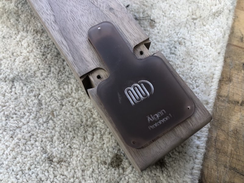
It’s hard to photograph that the cover is slightly too large, given that in effect it means the cover entirely obscures the cavity, so you’ll just need to trust me on this one :) When you laser-cut something the cut isn’t zero width, you always lose some material, referred to as the kerf. When I process my designs for laser-cutting the software I use lets me put in a slight offset to compensate for teh kerf, but in this instance it’s clearly a bit too much. I double checked against the template that I used to cut the channel on Älgen, to see if perhaps it was the case that my router bit was worn and not cutting far enough, but the cover didn’t fit that either, so it’s definitely an issue on the laser-cutting rather than channel cutting side (again, hard to photograph etc.).
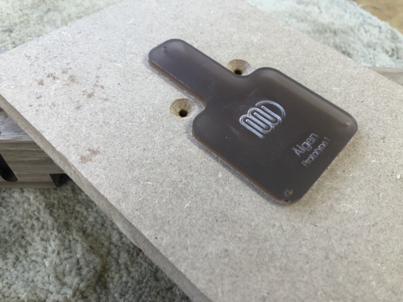
It occurs to me that for the wooden ones I made in the past I end up sanding the edges anyway to remove the burn marks, so they could well have been oversized too, but the sanding took care of that. So, back to Illustrator with me, and I manually tweaked the design I used last time to add a slight offset to the outer edge, bringing it in by half a millimetre, and I’ll recut it again for next week.
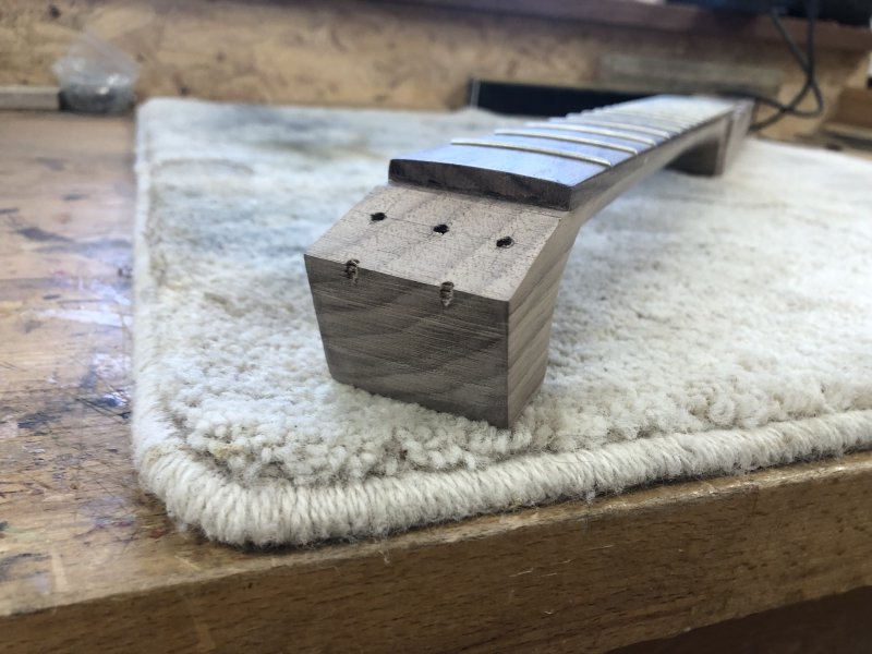
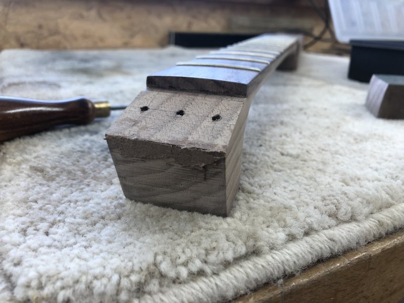
The only other bit I got done on Älgen this week was another bit of fixing up: I realised I had one more patch to do on this prototype, from a mistake I made in my template design, which put the neck template mount screw holes too close to the tip of the guitar, so when I finally put everything together there were two small nicks from where the template screws were visible:
If I was less pressed for workshop time, then I’d have gone all kintsugi and filled them with gold, but as it is I really need to wrap up this prototype build, so I just went my usual route of sawdust and wood glue:
I did this when I got into the workshop on the assumption that I’d work on the Delfin build, and then swap back once this had been left for a few hours to dry, but alas I quickly got blocked, and thus had to call it a day in the workshop and went home to do CAD instead.
Delfin
The first task I needed to do next on the Delfin was radius the neck. However, this didn’t go as planned, and in the end decided that it was time to stop trying to a radius necks using sanding blocks, which is what I normally do.
I’ve always used sanding blocks to put the radius into the fretboards on my necks. I once tried CNC routing it in back in the day when I did such things, but that left a lot of ridges that needed to be sanded out still, so in the end I just went back to straight sanding using a radius block - that is, the sanding block has a concave the same radius as the convex shape you want the fretboard to have. The problem with using a sanding block is that as a machine, the human isn’t very well built for this. As you push the sanding block along the neck your weight will shift, which means you take a little more off at one side at the bottom of the neck, and a little more off on the opposite side at the top of the neck. You can try to compensate for this by using two hands, but I find that just reduces it rather than eliminating it.
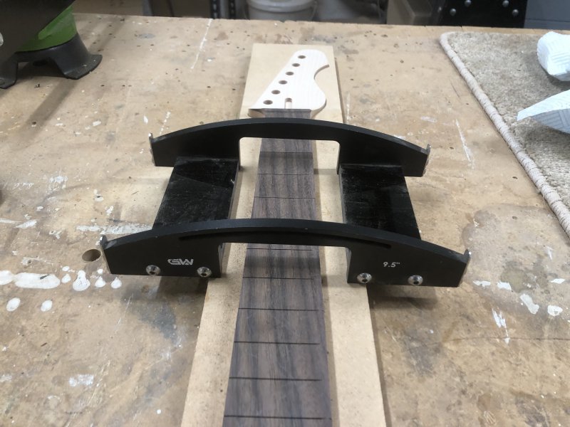
The best trick I’ve come up with is that I build a guide for me to press the sanding block against. I have these generic jigs for holding my necks in that that give me a straight edge parallel to the centreline of the neck (the edges of the neck itself being tapered), and I’ll usually try clamping a block of material along one edge, as you can see here from the last neck I made:
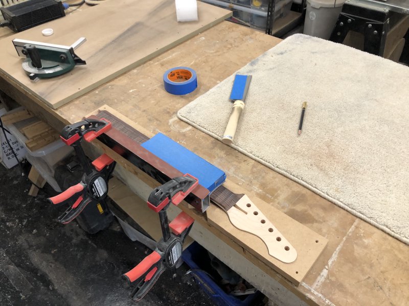
That above neck is a different scale length from the Delfin’s, and so uses a different jig. Although they look similar, the one I’ve made for the shorter scale length unfortunately doesn’t have enough space for me to repeat the above, but the gap is too large to successfully clamp a block off to the side as you can see in the opening picture for this section. I had a look through older blog posts, and the last time I used this jig I was still free-handing it and being very careful, and I don’t really want to go back to that, as it’s too high a risk of getting it wrong, and I know I can do better.
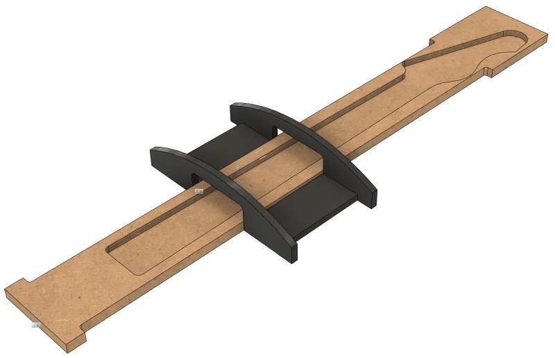
I could make a new jig that has enough room, but if I’m making a new jig, I’m going to make one for a better process. In the workshop I spotted Matt’s G&W fretboard radiusing jig, which is designed to be used with a palm-router:
As you can probably infer, the idea is that the jig lets you move the palm-router side to side to get the radius, and then you slide that jig along another fixed frame for the length of the neck. This seems to be a much better solution to what I was doing, so I quit the workshop, and a bit of Fusion 360 work later, and I have a new template design:
I’ll ask Matt to review my plan first, but I figure this will make things a lot more reliable.
Whilst I was in Fusion 360 I also went to design a template that I’d been dragging my heals over for some time, one to let me route out the slot for the ferrule block I plan to use to anchor the strings on the rear of the guitar. And after I thought I’d designed it, I realised that although I’d resolved one issue, I still had another show-stopper, which has caused me to rethink what I’m doing here.
Backstory: there are two ways strings are generally mounted on Fender-style solid-body electric guitars: either the strings are mounted purely on the bridge, which is what’s known as a “top-loader”, or the strings go through the body from the back, which is known as a “string-through” body. I have a Fender Mexican Telecaster which is a top-loader, but every guitar I’ve made has been a “string-through”, on the grounds that I do buy into the idea that this does a better job of clamping the strings to the bridge saddles. Indeed, my Mexican Telecaster, which was the the cheapest guitar Fender made that year that still had a Fender badge, is the exception: the vast majority of Fender’s guitars with fixed bridges are string-through, including this model from most other years. Gibson style guitars don’t run strings through the body, but the tune-o-matic bridges they use have quite a different geometry (in part thanks to the angled neck that Fenders don’t have), and thus they have a different story regards the clamping angle of the string. I have to confess, I have no hard evidence that either string-through or top-loader is better, but I do know as a builder that most players of this style of guitar (of those that know to care) want string-through.
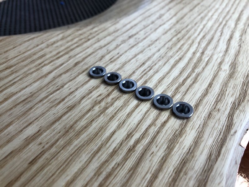
The problem with string-through guitars is that the strings need somewhere to anchor, and that somewhere is usually individual string ferrules. These are little metal buckets into which the string ball-end sits. Here you can see them on the back of The Corvette build:
I’ve used these ferrules on all my builds to date (Älgen aside), and they’re a pain in the neck to work with, as I complained about last time I had to fit some, and I’m sure if you searched back further then you’d probably find I make a similar whinge each time.
There’s three things I dislike about the ferrules:
Firstly, they do not come in perfect diameter sizes to match drill bits, at least my drill bits, so I end up having to manually ream the holes to get them to fit, which is very tedious. I suspect if I build made guitars then I’d go to the effort of finding a set of ferrules and a drill bit that matched, but given I make only a couple guitars a year that has not yet become a justifiable expense. I guess the point here being that this is solvable, but hasn’t been a practically solvable on yet at my scale. If I CNC’d the bodies (before Adan gets there :) and always used the same ferrules from the same supplier, then this would also be a non-issue, but I don’t, and so it is.
Secondly, drilling six holes by hand and lining them up perfectly is a pain. My first guitar has ferrules that look how British people’s teeth look compared to Americans’; since then I’ve got better at this, using jigs or by better drilling technique, but it’s still a pain and an unnecessary risk of turning a good guitar body into a bad one very quickly. Again, my lack of CNCing is my undoing here.
Finally, if you look at the above picture you can see that the ferrules protrude slightly, because most ferrules have a little lip on them, and using my drilling technique I can’t reliably create a recess for that lip. If I was CNCing these then I’d also cut out the little ledge to properly recess them. But I’m not, and so they aren’t.
All of which I guess is a way of saying that in my book individual string ferrules make a lot of sense if you’re CNCing your guitar body, but are a right pain if you’re doing things by hand like I tend to.
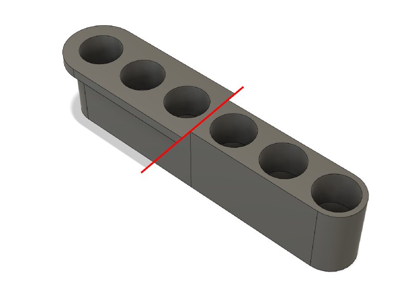
So, step back a couple of months and I decided that enough with individual string ferrules, I’d switch to using a ferrule block instead, which you can see in this CAD model:
This block solves a couple of problems, but I belated realised (after buying one of the blocks to measure up) it does not fix all of them, which seems kinda obvious in hindsight (but if I was good at realising problems early, then you’d have nothing to read here).
The main benefit of using a block is that it takes me back to using a router to make a channel for the block, which removes the first two of my problems: I can use a template with a small follow-bit to route out the pocket for the block, and everything will line up and be the right size without needed to ream the hole. Obviously I need my template to be spot on size wise, but it’ll be laser cut, so I can just make a few with slight offsets up and down size wise and test them to find one that matches perfectly.
This block, just like the individual ferrules, still has a lip around the top surface, which is annoying, but just means I need a second template that is slightly larger than the first.
The problem with this approach is how to attach this template to the body? If I could just cut everything in one pass then I’d eyeball it and use masking tape to secure it, but I’m going to need to use two templates, and so I would want screw holes that I could use as a reference point. Pondering this it occurred to me that I’ve yet to cut the cavity for the electronics, so I can mount it using the wood there, and those unsightly screw holes will go away when I make that cavity:
Job’s a good’un, right?
Except that I then realised that a laser-cut template will not be thick enough for me to make the recess for the lip that is so shallow, as smallest router-bit I’ve found for jobs like that is still 6mm deep or so, and the thickest material I can reliably laser cut is about 5mm, leaving just 1mm or so for the router-bit bearing to sit on, which is too risky for my blood: I’d want most of the bearing to be on material, which means I need a template that’s about 10mm thick, which means I’m over to the CNC-router, as the laser-cutter I use can’t cut more than 5mm or so. CNCing also means MDF most likely, and I’m less convinced that between drill bits that wander and how easy MDF is to damage compared to acrylic I’ll get the tolerance I want when aligning the two templates.
This all starts to make individual string ferrules seem like the better option, which can’t be right.
So I find myself asking, why is this even a problem? Why is that stupid lip there?
Here’s a cross section of the ferrule block in the body:
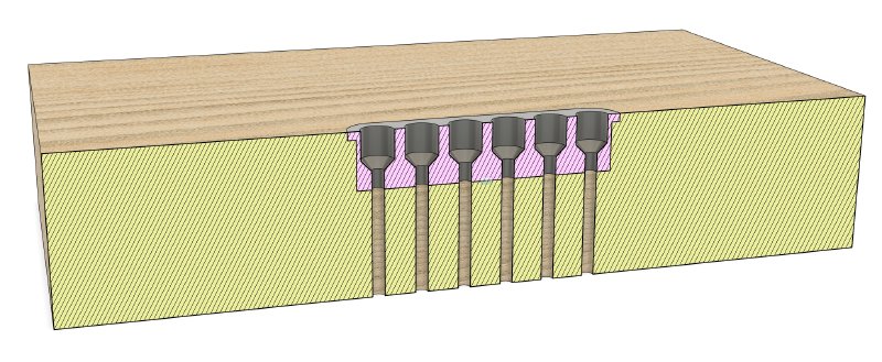
I’m going to go out of a limb here and say it’s nothing to do with the sound of the guitar, and thus it’s there for some manufacturing related reason, not for a technical reason to do with making a playable instrument.
In the diagram above everything is cut perfectly, what if I was to cut the channel for the recess deeper than necessary, which would then let me use a laser-cut template?
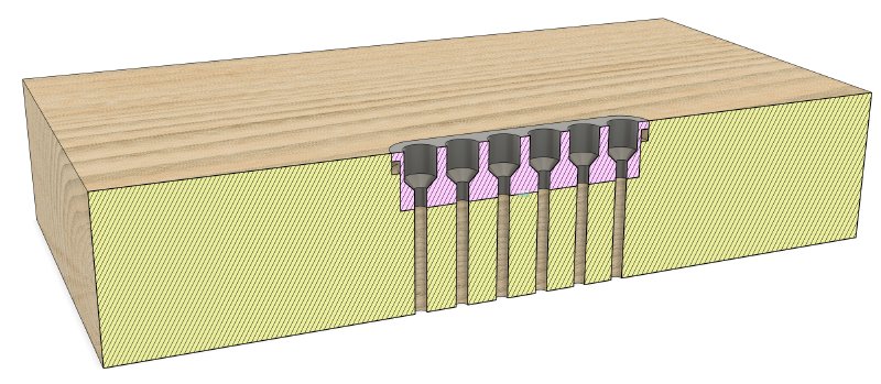
So long as the bottom section has enough depth to stop the block sliding around, I don’t think there’s a technical problem here as I don’t think the purpose of that lip is to be load-bearing (though it does offend me knowing that it’s a bodge).
So if the lip isn’t meant to be load-bearing, why is it there? My assumption is that it just looks nicer having a large plate of the back of the guitar, but keeps the material costs required to make the block down, as from a structural perspective it doesn’t need to be that big. Certainly if I remove the lip in my CAD model it does look less balanced:
So in summary my theory is that the lip is there to make things look nice, but is adding quite a bit of technically unnecessary complexity to my build process. As an engineer, I’m quite offended.
So what’s the solution here then? I think I have top obvious options: firstly I just cut the recess for the lip lower than is necessary, or I can just 3D print my own ferrule block that doesn’t have a lip :)
Option two is quite an extreme response, given the cost that would be involved for the benefit. Whilst I normally am happy to 3D print bits, I only do so when there’s some functional advantage of the costs make sense; here the replacement would be about five times the cost to 3D print and offer no functional improvements beyond not having a lip. That said, this part mates up with the bridge plate on the front, and on the Delfin I am going to 3D-print the bridge plate, so perhaps I can do something interesting here?
But I suspect 3D printing doesn’t really make sense in this instance, so in the mean time I’ll test out the overly-recessed outer cutout method to see how that works on some test pieces and see if I’m satisfied with that result.