A Week in the Shop
Published 10 Jun 2023
Tags: älgen, blues deluxe, electronics, fretwork, hästen, inlays, lacquer, noel gallagher, spraying
Another long week-in-the-shop, but unlike the deep-drives into issues of the last two weeks, this one is just because I’ve spent a lot of time in the workshop as the deadline for Liverpool Makefest hurtles towards me, and I start to get stressed about being prepared. It’s three weeks away now, but one of those weeks I’m now travelling unexpectedly, so the pressure is on to get things done in time. I had hoped to have a second guitar finished in time, but I suspect that’s now a bit ambitions given the constraints of finishing, but I definitely need to get one ready to be played by the public :) So if you’re in Liverpool on July 1st, do stop by Liverpool Central Library and say hello. I note there is now a 60s fancy dress theme for the event this year, but given the lack of time to prepare I’ll go dressed as I usually do, which to be honest probably could be mistaken for 60s garb anyway…
This week I also got the exciting news that I’ve also been accepted to give a talk at the Open Source Hardware User Group’s annual meetup OSHCamp, which is part of the Wuthering Bytes festival at the end of August in Hebden Bridge. This talk is meant to be a bit of a follow up to the talk I gave at the Wuthering Bytes festival in 2019, this time talking about the techniques used in building guitars from a hybrid-manufacturing point of view, mixing in 3D-printing and generative design. The talks list for OSHCamp this year looks quite diverse and interesting this year, so looking forward to the event!
Älgen
The highest priority task on my todo list this week was get spraying the body for Älgen. Last week I’d done some tests of the impact of acrylic lacquer the 3D-printed nylon of which the body is made by spraying some of the test prints I did. Given these hadn’t melted, and indeed once sanded back had quite a nice feel to them, it was time to get the main body done.
Before I could spray the main body parts though, I needed a way to hold them stable whilst I did the spraying. Normally when people spray guitar bodies they will have a beam of sorts that attaches to where the neck-pocket, which can then be held and rotated, but Älgens body comes in two halves that attach to the side of the main core of the guitar, so that approach wouldn’t work. To remedy this I decided to build myself a sort of mini-body to attach the sides to whilst I sprayed them.
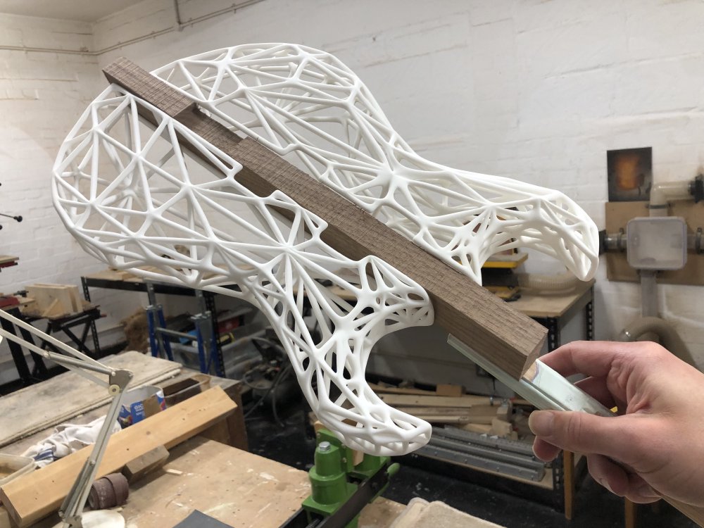
Thankfully I tend to hoard off-cuts from builds until they’ve shipped, incase I need to do any fixes or finishing tests, and so I found a long strip of walnut that I’d cut off the side of the blank I’d used to make the core body of Älgen that I could use for this. I also dug out the templates I’d used to route the dove-tail joints used to join the 3D-printed parts to the body, and proceeded to repeat that process, albeit on a smaller scale.
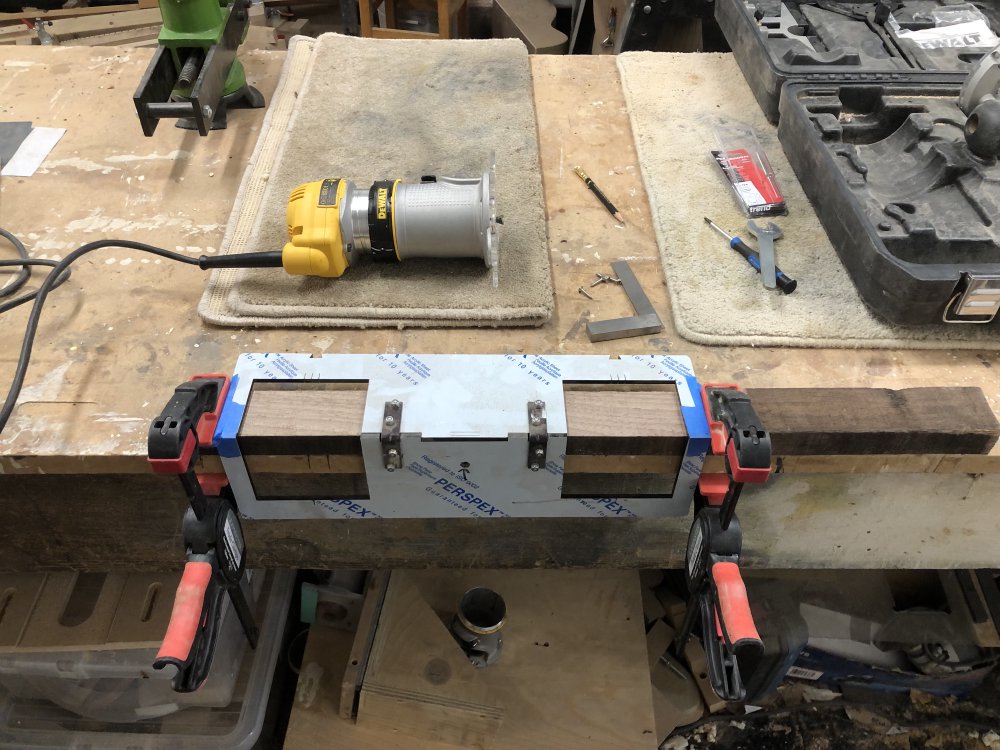
These templates are designed to work with a custom base plate for the palm-router, and allow me to cut both the dove-tail slots into which the 3D-print will slide, and a recess on the end of the slot that will be the home of a plate on the 3D-printed part which lets me use a screw to hold things secure.
It took me a couple of goes to get the depth correct, which was a nice reminder of how fiddly the joint was to make in the first place, but in the end I had one side done:
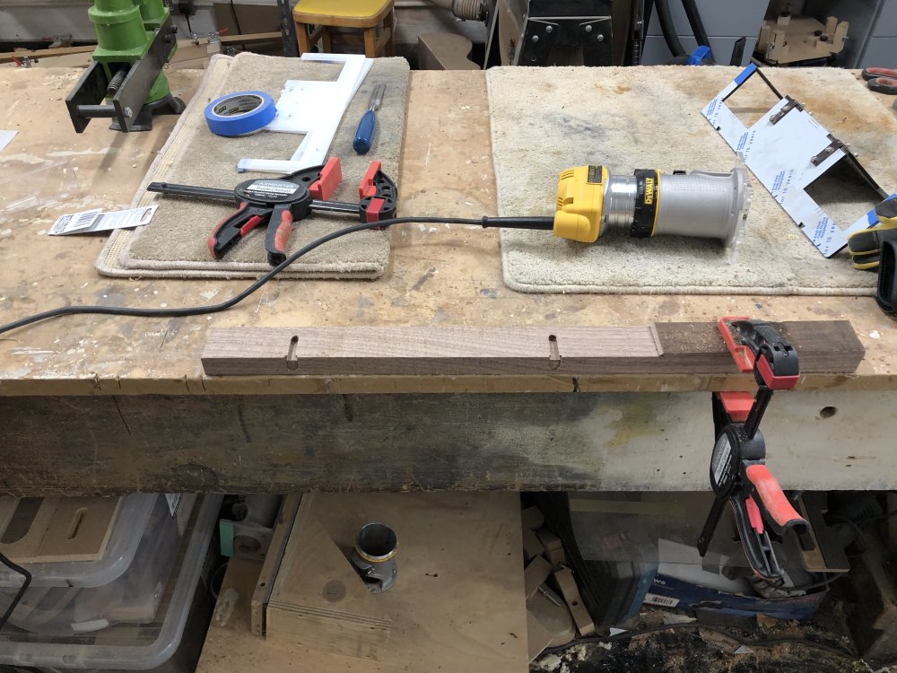
For the other side I had to use a second version of the jig (which you can see floating around in the background in the earlier pictures), because although in CAD the two 3D-prints have the same mount spacing, you get some level of shrinkage in 3D-prints, and the two sides actually differ in the mount spacing by a millimetre or so, and thus I needed two jigs. This does make me concerned about the repeatability of this process as I build more of these, but those are concerns for another day.
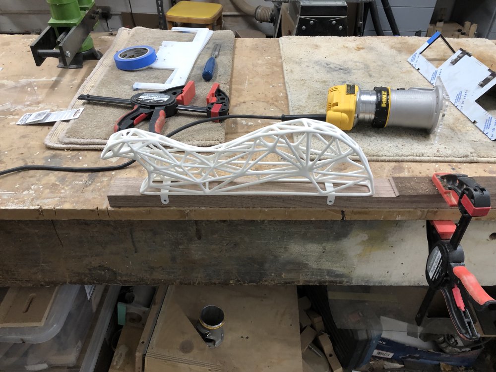
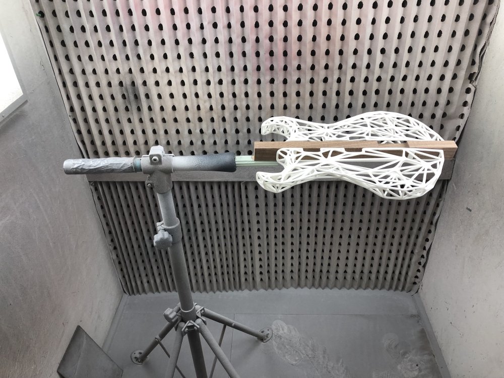
With both sides routed, I could now attach the beam that is normally attached to a guitar body’s neck pocket, which will sit in the clamp system we have in the workshop’s spray booth:
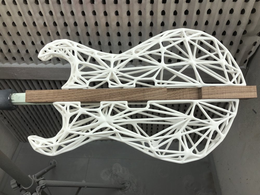
And with the sides attached it starts to look like a regular guitar body :) You can see in the next photo I had to cut a notch for where the recessed bridge is to ensure that bit gets coated too, as your fingers rub up against that whilst tuning.
And voila! I was now ready to spray a protective lacquer onto the body.
Before I did that I went over the body parts in detail trying to remove any dirt they had picked up, any fluff, etc. It took me a while, and included using both tweezers and a clean paint-brush to tease out bits from inside the mesh - thankfully the light boxes in the spray booth make this an easy task. I suspect this is the first time I’ve really examined every little corner of the 3D print in detail, which was a weird realisation given how long I’ve had these parts. In the past I’ve just seen them as small parts of a bigger thing, but here they were the main event. It was interesting to see some of the interplay between the vertices of the mash as they come together in peaks or cross each other with creases.
I also have to confess I took this next photo as a sort of record, incase the lacquering process goes a bit Pete Tong. This is the first time I’ve sprayed something as a finishing technique, and it’s a bit of a crazy place to start ones spraying career on 3D-prints that cost hundreds of pounds to get made, but given time constraints, this is where I get to learn. I had intended to spray paint and lacquer one of my other builds first, but timing just was against this, as it’s this guitar that has to be ready by the end of the month. 🤞
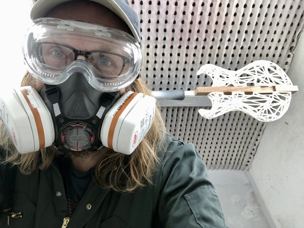
Here’s me about to get started - this is the look of someone who really should have brought a scrunchy to the workshop. If you run into me in the coming days and I have unusually glossy hair, you know why 🤣
I did two coats in the end before having to depart for the end of the week. I’ll sand this back before doing two more, and then probably two more after that based on what I’ve read, but we’ll just see how it goes - I’m learning on the fly with this one.
As I mentioned in the opening, the test prints actually feel pretty good once lacquered and sanded, certainly better than the raw print did, which had a slightly rough texture to it. My suspicion/hope is that I’ll be kicking myself for having procrastinated on this for so long, assuming the patient survives the surgery…
Hästen
During last week’s adventures working on Hästens neck, I mentioned that I was short of dot-inlay material (at least, that will work on lighter maple woods rather than the darker rosewood/wenge style fretboards I more commonly use), and so I ordered some new inlay dowels for this and future necks. I decided rather than just go with plastic again, to give metal dot-inlays a go - why not change things up when you’re short on time? Whilst ordering some drill-bits in fine increments (an essential for dot-inlay work, as the dowel is rarely perfectly the diameter it claims) from Macc Models I also spotted they had various metal dowels in 2mm diameter, so ordered some brass and silver-steel ones to try.
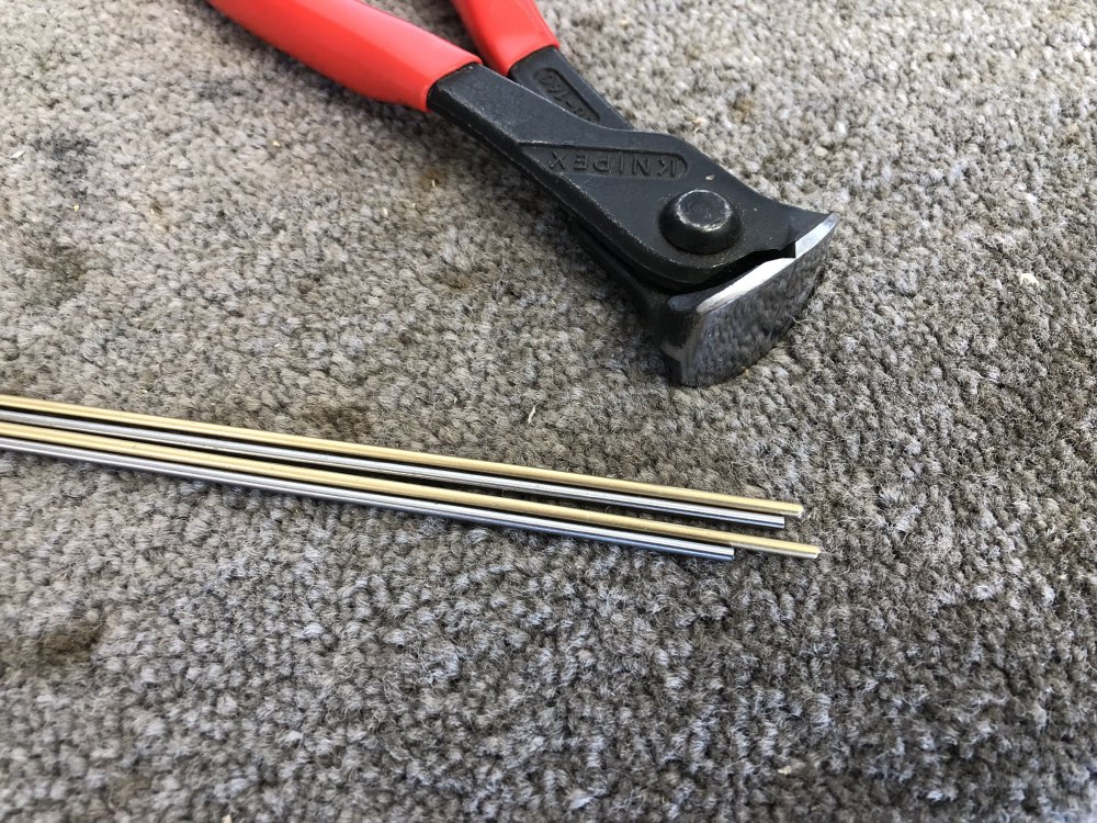
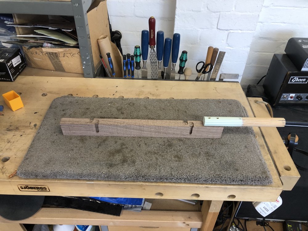
I was concerned that metal-dowel might present a challenge in terms of being harder than the wood material unlike the plastic dowel I use that is softer, perhaps meaning if trying to sand smooth the area would I remove more wood than metal leaving the inlays proud? Thus before I attempted to apply this new material to the neck, I first did some testing in an off-cut from the neck. I drilled a series of test holes and in each I glued in the end of silver-steel dowel, snipped it, and repeated until I had a small row of samples. The one notable difference at this stage was that I did have to lightly sand the end of the dowel each time to put a slight taper on it, as snipping it caused it to deform a little.
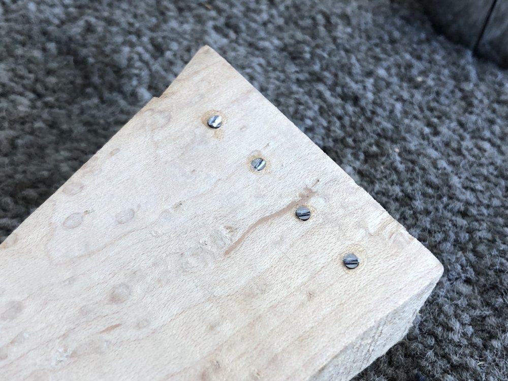
I then treated them like I would fret-ends: I got them as close as I could to being level using a rasp, before using some 80 grit sand-paper and working up through the grits until I had some nicely levelled inlays:
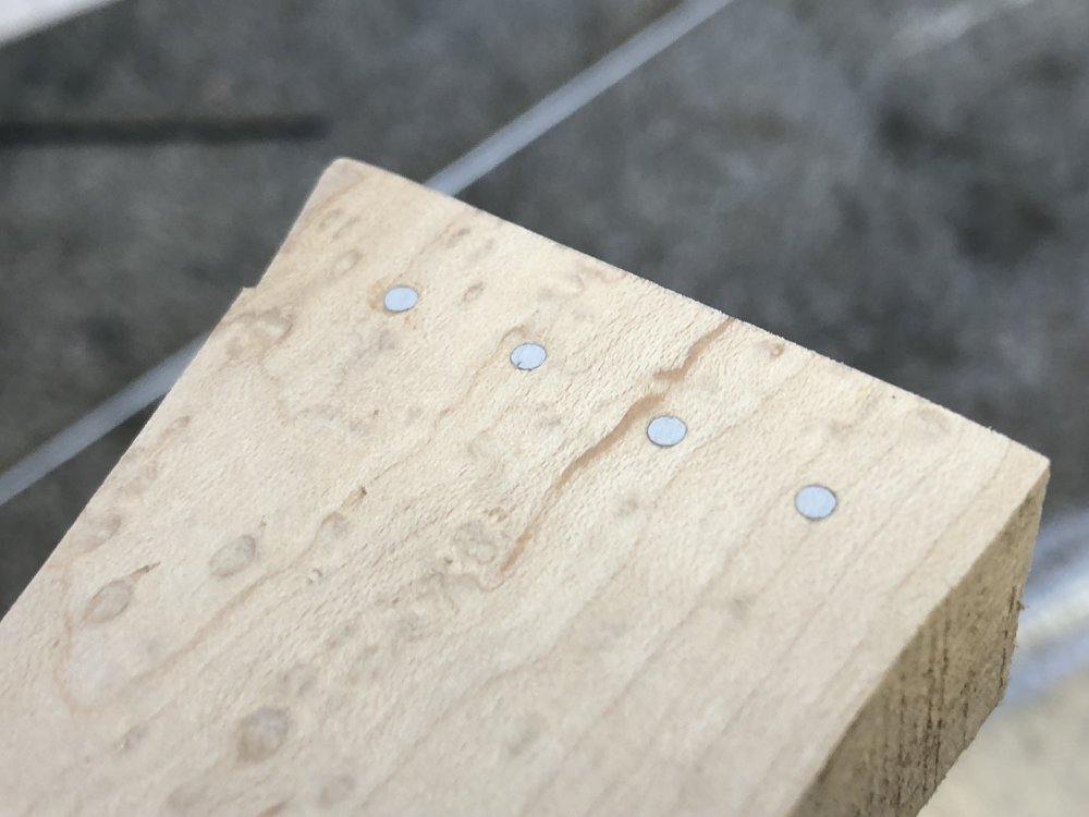
This was my second go: the first time I didn’t use the rasp as much and switched to the sand paper sooner and that didn’t work so well - you need to get rid of the snip mark with the rasp, and only then get the polish on with the sand paper.
So this was both a technical success, in that the dowel did level well, and a design success, in that I like the end result in terms of inlay visibility against the maple wood. The contrast isn’t as high as the black plastic dowel I’d normally use, but I think it’s visible enough, and it reflects nicely as you move in the light. So with that I went and made the inlays for the neck using my new dowel:
After I’d glued them in I didn’t yet process the ends to make them neat, I’ll do that as I do the same for the frets.
Before doing the fret work, I next wanted to just tidy up the fretboard from last week’s cutting of the radius using the palm-router plus jig method. However, unlike my previous use of this technique on a rosewood fretboard, which had resulted on a nice smooth finish, I realised as I checked in the light that the maple had not been so well behaved, and there was obvious rough/smooth banding from the cut of the router bit:
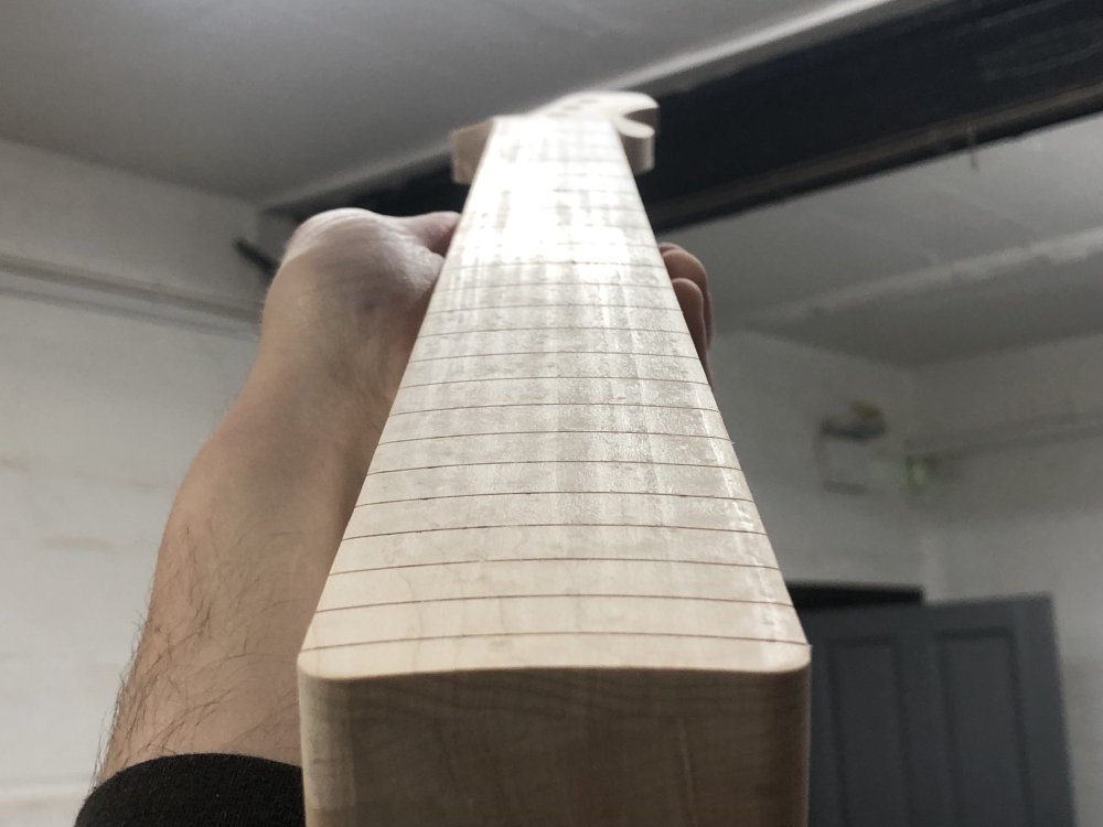
Thus it was out with the sanding tools to get the fretboard uniformly smooth:
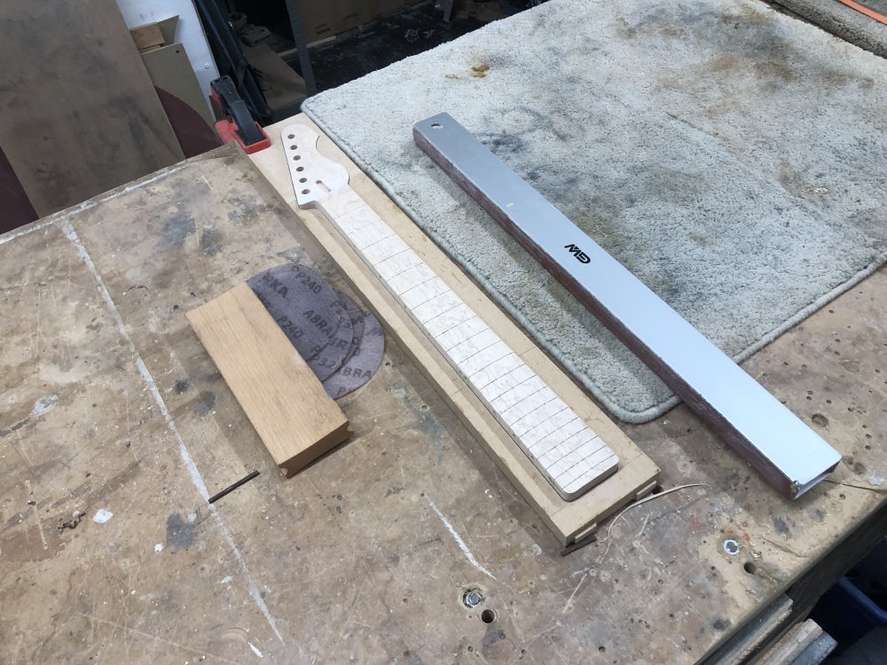
Because I need to be cautious here not to over sand, I was regularly switching between using a long sanding-bar, to ensure the fretboard stays straight, and a radius block, to ensure I keep the correct radius, and in the end this took the better part of an hour. I aldo rolled over the edge of the fretboard at this point to, as you don’t want a sharp edge to your fretboard.
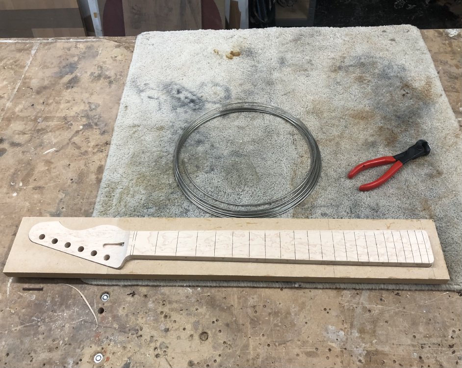
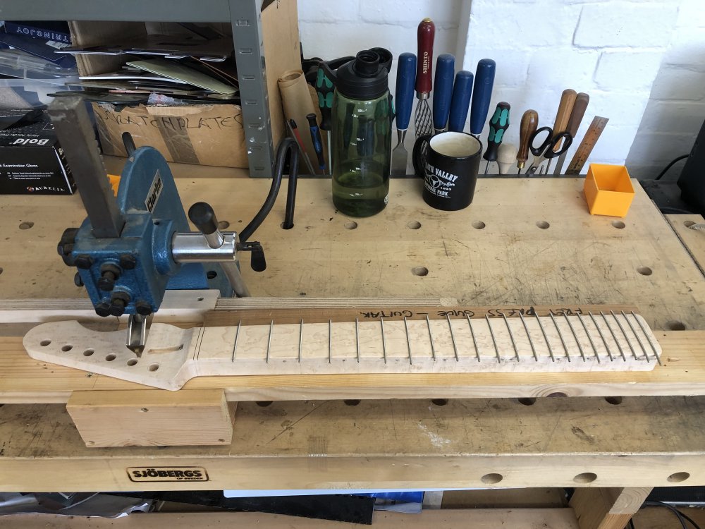
With the fretboard tidied up, next up it was time to put the frets in. It is somewhat weird to me these days how much this has become a task that I just move through as a matter of process, whereas before it was the biggest challenge I faced on any build and filled me with dread. This is down to a combination of the use of the table-saw I described last week for cutting the slots, and to the use of the arbour-press to get the frets home. Just having the right tools for the job, whilst not a show-stopper if you don’t have access to them, really do make a world of difference if you do. If I was to move workshop and needed to get back any of the tools I’ve discovered in this workshop, it’d be these without a doubt.
For the arbour-press, which is a general workshop tool, you need both a press bit (the part that will squash the frets) and an adapter that will connect the bit to the press itself. In general you need to buy a bit that matches the radius of your fretboard, but my workshop-mate Jamie made this neat variable radius that is made of two halves held in place by magnets that will adjust based on the radius of your fretboard. Given the number of different guitars that pass through this press from the three builders we have in the workshop, this saves a lot of messing around changing the bit each time.
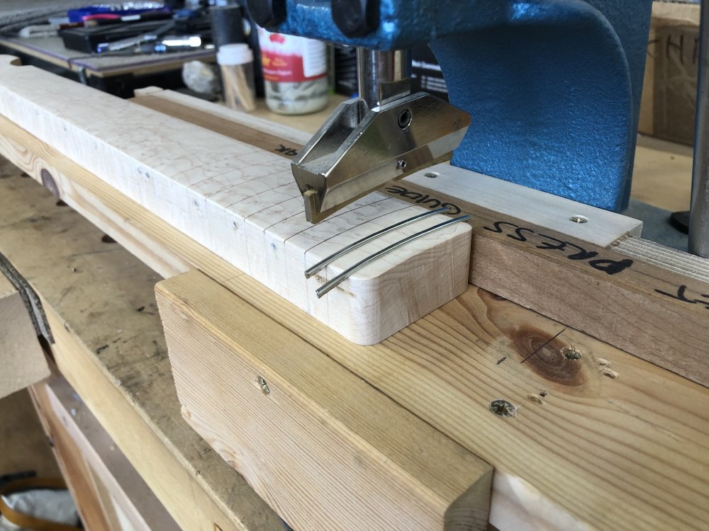
All that being said, I still take time and care over this, as this is one of the bits where if I mess it up I’m not making a musical instrument. But because everything is much more controlled the whole process is much less stressful than it was before and the results much more consistent.
Once the frets were in I did a bit of a hair cut:
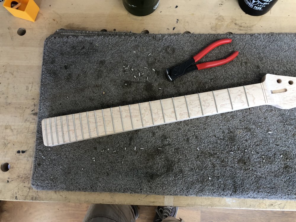
And that’s where this neck rests for this week.
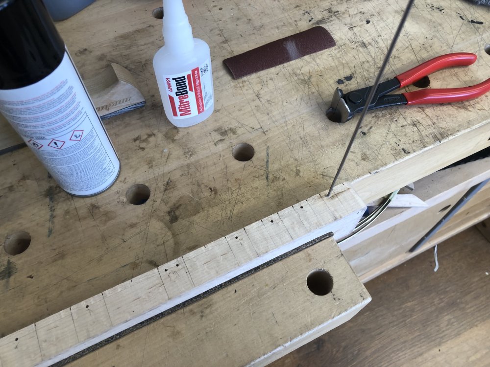
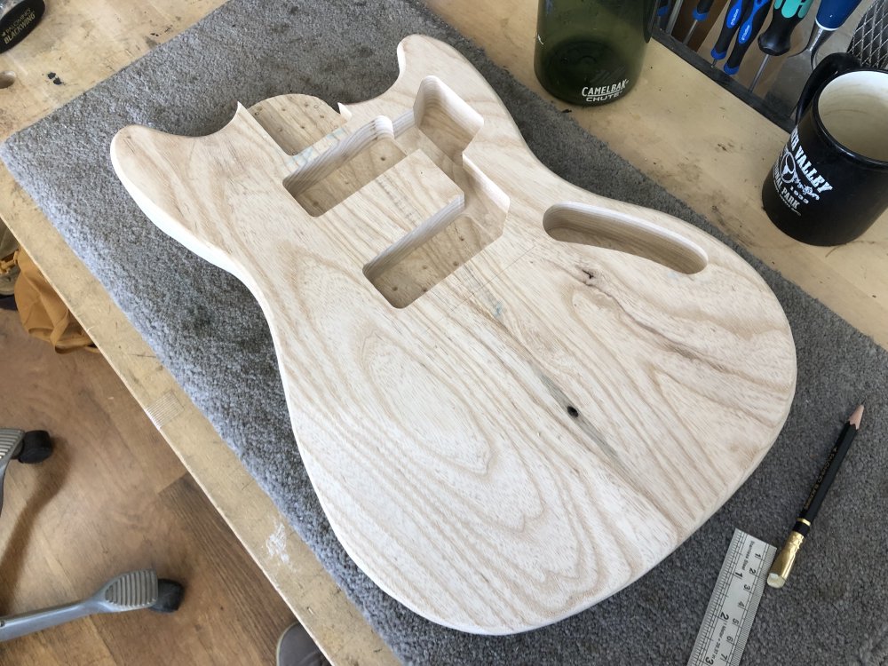
I did do one other job on this guitar, which is mark out the scale-length point on the body:
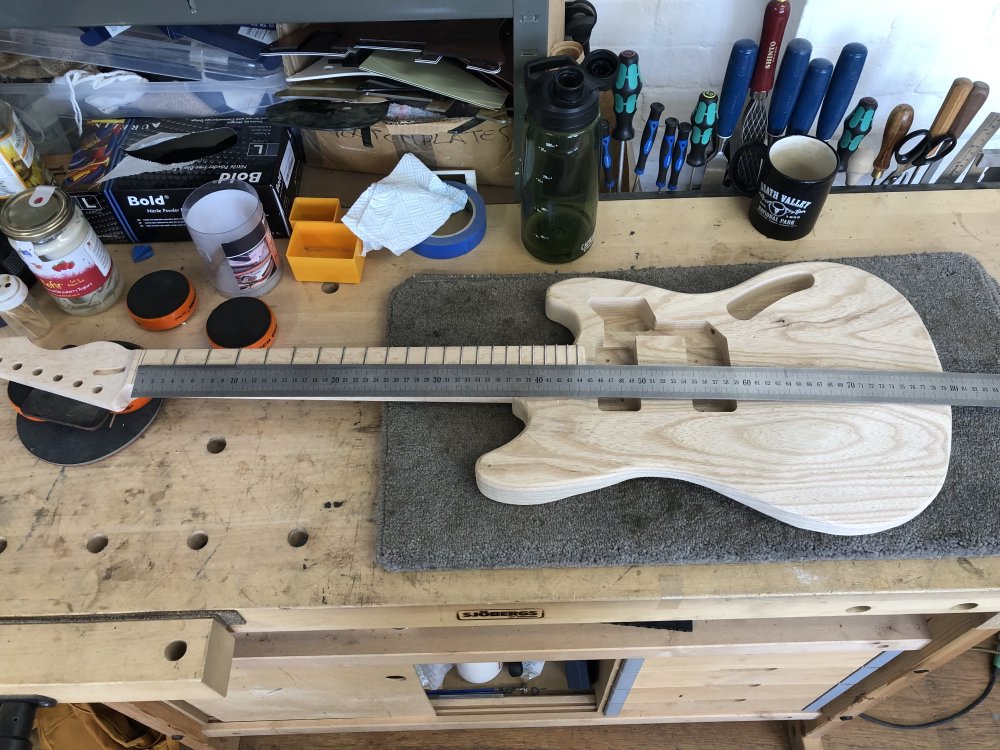
If I was doing everything by CNC then I’d know where the scale-length point on the body would be, but because I manually set up the position of the fret slots, that means the nut position may move by a couple of millimetres, and so I liked to do this by hand to check it’s perfect for a given guitar.
Now that I the scale-length reference next time I have time I can figure out the bridge position and start making the holes for that and the string ferrule, which are the remaining bits to do on this body.
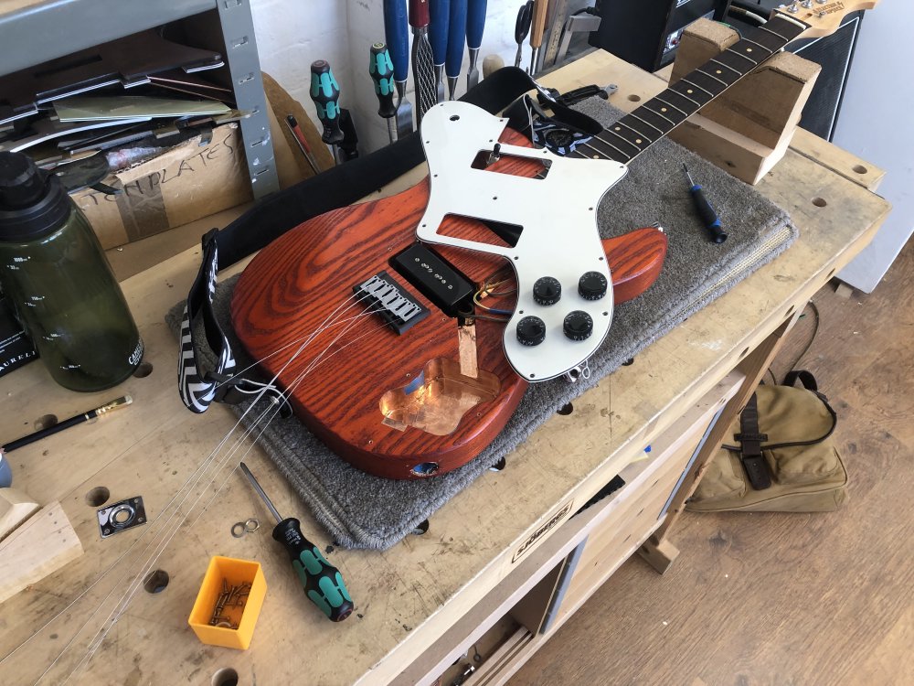
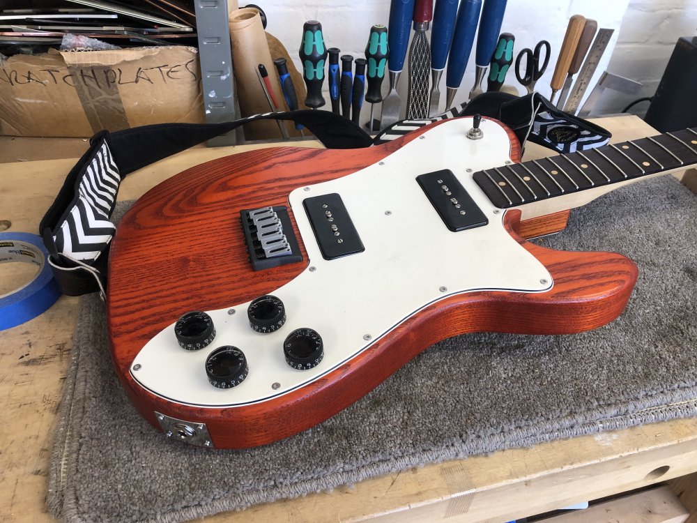
The Blues Deluxe
This was meant to be a fifteen minute job. I’d noted a few weeks ago that the jack on my daily-driver guitar, The Blues Deluxe keeps coming loose, noting:
I remember when I built this one, I’d got a jack plate that wanted metric jacks, and I only had imperial jacks, so I’d just got the first jack I could find from somewhere to let me finish it, but it’s never been the most stable of mounts. It comes loose just infrequently enough that it doesn’t motivate me to do strip the guitar down to fix it.
Well, it came loose again and I decided that this was silly, I have a parts draw full of good jacks, and it was time to just swap out the duff one in this guitar for a better one. This is a pain, as it involves removing all the strings so I can remove the pick-guard, which is why I’d been putting it off, but enough was enough. So the plan was just to open the guitar up, de-solder the old jack, fit the new one, and we’d be on our way. Fifteen minutes tops. Ten if I was quick at getting the strings back on. So of course I started this at 5pm as a final act for the day.
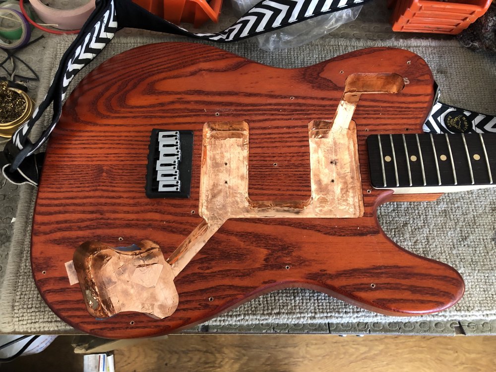
I did what I thought was the job, and then went to test it, and… nothing. Not a sound. I was fairly sure of my soldering, and I’d done some checking with a multimeter, so I was happy it wasn’t that I’d soldered it poorly. So I open it all up again, and eventually I realise that the problem is the new jack, being a more sturdy one than the original, was also slightly bigger, and it was shorting out on the copper tape used to insulate all the internal cavities.
I originally made this guitar back in 2017, and it was one of a pair I made together that were just the second and third guitar bodies I made - you can indeed see me doing the original electronics back in this early post - and I didn’t get the hole for the jack quite perpendicular to the outside edge, and so it was quite a tight fit, which is why the new jack is pressing against the copper tape.
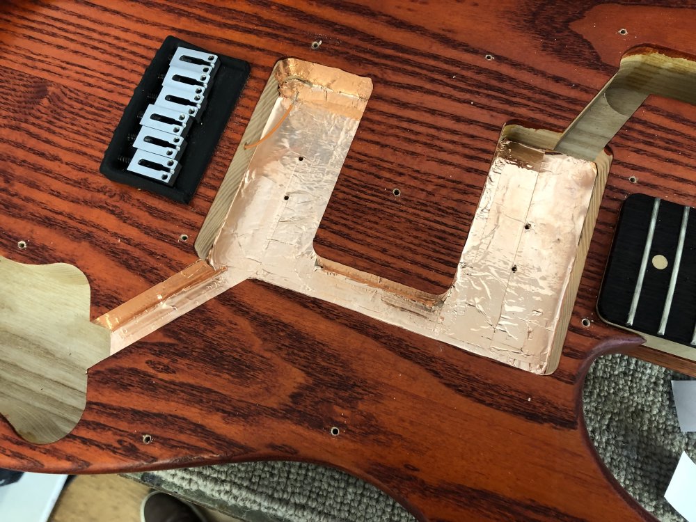
Given it was late in the day and I didn’t want to start making structural changes to this body, and given I don’t gig with this guitar and so noise isn’t really a significant issue, I figured I’d just remove the copper tape from inside the hole that goes from the jack-plate to the main cavity for the tone and volume controls. This I did, and just as I was closing it back up I thought to check that I still had an earth on the shielding, as one of the contract points would have been the jack-plate, which is now isolated from the rest of the internal shielding. In theory, this shouldn’t have been an issue, as there were several other places that the connection should happen. Unfortunately, I found that there was no continuity.
At this point I put the guitar back into the gig-bag and put it into the workshop storage room - this was a patient that was now in for an over-night stay 🤒
The next day I opened the guitar back up and did a full continuity check, and found something quite interesting: it wasn’t just that I’d lost the connection from the jack-plate to the shielding that was the problem, but the fact that although each bit of tape should have been connected to every other bit of tape, as the sticky stuff on the back should conduct, there was quite a high resistance between each bit of tape and it’s neighbour, which is why the continity tester was saying things weren’t connected.
I’ve no idea if it is the case that I didn’t check things properly when I first put it back together, or somehow over time the glue on the tape has changed and now is no longer as conductive as it once was, but this meant I had a problem. I was relying on the tape to provide a constant access to ground across the guitar, as this is how the bridge was earthed and the toggle switch was earthed, and explained why I’d been getting some static noise from that switch occasionally when I touched it.
Unfortunately, there was only one solution for this. Despite not really having the time to do it, I ripped out the entire lot of copper tape and re-insulated the body, ensuring as I went that I had continuity everywhere.
This took two hours all in, which given my deadlines isn’t the best use of my time, but once I’ve got the guitar open it would have been stupid not to just get it done there and then, particularly given this is my daily driver guitar.
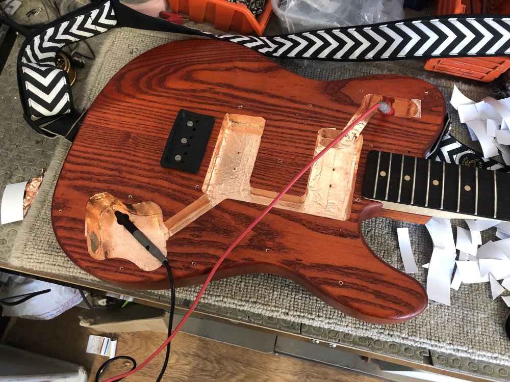
Once I was happy everything was in, and I also added ground wires from both the control pots and the switch to the shielding, rather than as before relying on the tape on the back of the pick-guard contacting the tape on the body as I had done before.
It’s now back together and back home and back in use, though having it in the workshop did make we wish I’d had had the time to re-do the fret ends, as my fret game has come along way this last couple of years, and the new necks I’m making are so much better than what I did for this guitar. But I definitely don’t have time for that right now, so that’ll be deferred until it next needs its strings changed!
Noel Gallagher on TPS
I got into playing guitar in the 90s, which was a bit of a comeback decade for guitar after the 80s. This means that I’m very familiar with the work of Oasis, one of the biggest bands in the UK of the mid 90s, and even had the guitar tab book to “What’s The Story (Morning Glory)”. I never really followed the soap opera that was attached to the band, but it’s hard to ignore the impact Noel Gallagher’s song writing had, and how they went from just a loud and leary band with Definitely Maybe, to breadth of song styles seen on its successor.
Given their personal reputation, I was a little reluctant when I saw the TPS crew had interviewed Noel Gallagher recently, but it was for nothing, as this is a wonderful deep dive into Noel as a musician and song-writer:
Noel walks us through the guitars and amps he used as he and Oasis expanded, he shows a healthy mix of amazement at technical wizardry and enthusiasm for a simple guitar into amp turned up loud. It was fascinating stuff, particularly given how much he defined the sound of an era in music (at least in the UK). I like interviews like this (similar to the enthusiasm I expressed for Cory Wong’s podcast series a few weeks ago), as I put a lot of effort into building these tools, it’s nice to be reminded of their purpose and place and the impact they can have when applied, which is really why we do this.