A Week in the Shop
Published 2 Apr 2023
Tags: 3D-printing, amp, colour, form 3, formlabs, fusion 360, stain, verkstaden
Usually I like to try and tackle just a couple of projects in a week, but this week I didn’t get a concentrated run at anything, so I have a bunch of smaller updates instead. It doesn’t feel like progress, but that’s one of the benefits of these week-notes - they remind me that a bunch of small bits of progress does add up.
A custom volume control for älgen
I mentioned last week that I wanted to print a custom volume control for Älgen, but didn’t think that the Formlabs Form 3 resin printer at the local maker space had any clear resin so was pondering a Shapeways order. I happened to pass through Makespace on my way to a meeting for the day job, and I was surprised to discover there was in fact resin, only because I didn’t expect there to be any, I didn’t actually have a proper design in Fusion 360 that was printable. So in (for me) record time I went from idea in head, to model in Fusion 360 to STL file to in progress print :)
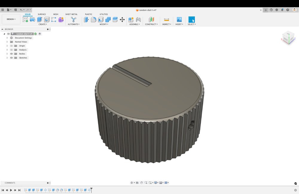
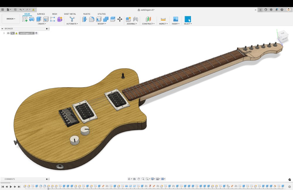
If you’ve seen screenshots of my guitars before (like the one that follows later in this post), then you’ll recognised this control as the generic placeholder control I usually use, only here I’ve added a lot more detail. For example, it has a texture to the outside to improve grip, it has channel for a grub screw to affix the control to the potentiometer shaft, and not visible there I also added a toothed inner recess for the potentiometer shaft to sit in. In theory you’d not need the grub screw given I’ve put teeth insider to mesh with those on the potentiometer, but in practice the resin prints aren’t really strong enough, so need the grub screw to properly secure them.
With all that whizzed up it was over to the Form 3 to kick off the print whilst I headed to my work appointment:
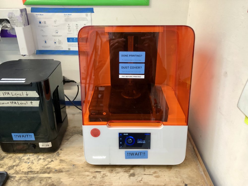
Once back, I found waiting for me a finished print - living the on demand manufaturing dream :) After cleaning up the print in the IPA bath and UV curing machine, the print looked quite the thing:
One thing that I found interesting using the newer Form 3 printer versus the Form 1 that I used to use to print things like this is that the new printer seems to work better with having the print flat on to the base plate, rather than at an angle. It used to be advice was to have your part at an angle, which made the printers job easier (aka, less likely to fail), but that meant you’d get support points on the sides, which then I’d have to sand down. Here I’ve kept all the supports on the underside of the piece, which means this is good to go with no sanding etc. - this is a definite game changer in terms of practicality of using the Form printers for production parts.
Given it was a rush job, I’m pleased with how it came out, as with the textured outer really feels good to hold. I’m less pleased that I chose to put the grub screw shaft opposite from the indicator, which works fine on opaque prints, but might be confusing on this instance - we’ll have to see when it’s cleared up and installed.
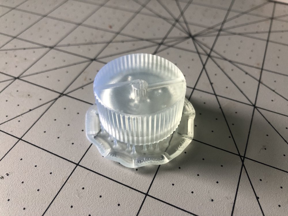
Once in the workshop, it was a quick moment to remove all the support material from the print. This did reveal that there was still some uncured resin lurking under the support material, which is a bit annoying, but not a total surprise based on past experience:
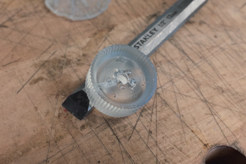
Clearly the IPA bath got into this area, as most of the surface is clear, so I assume there were just some air bubbles around this area that stopped the bath fully washing it. Not the end of the world, particularly as all this is on the underside and won’t be visible once installed, but something to consider depending on what you’re printing.
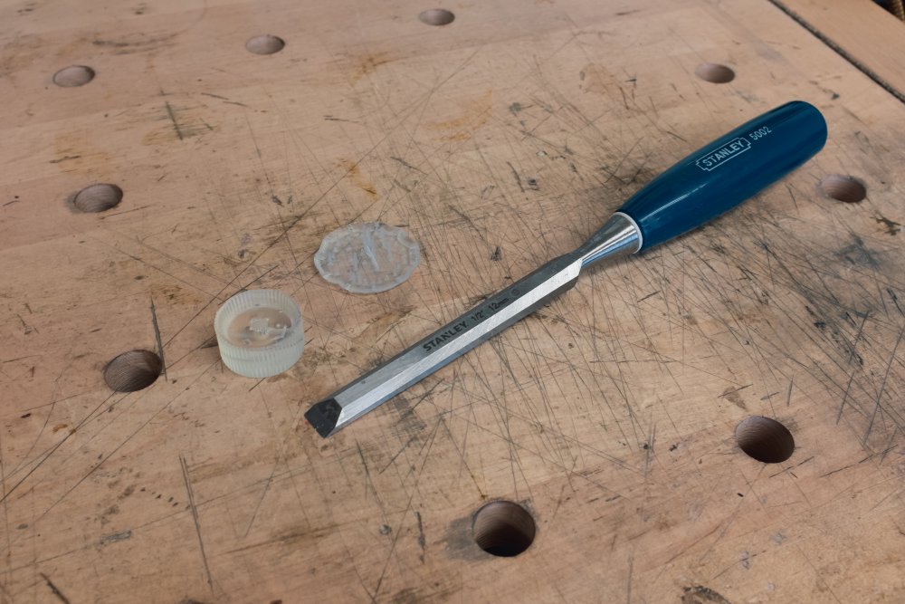
With the print cleared up of gunk using a cloth, I can now do the next step of prep: tapping the hole for the grub screw.
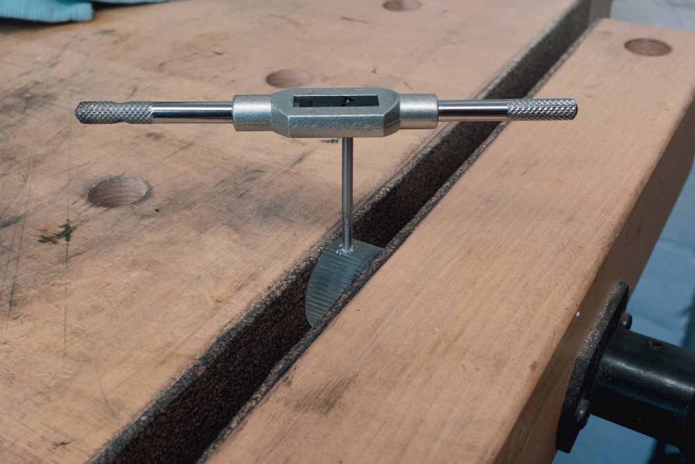
I’m using an M3 grub screw, and so I printed the shaft for the screw at 2.8mm, which seems to be a good fit for tapping. Whilst you can just use the grub screw to thread the hole in the resin, the resin being reasonably soft, using a tap tool like this is going to give you a much better result. I think it was Aleric at Makespace who first turned me on to the use of taps rather than using self-tapping screws, and for things like this it’s definitely worth the time. A few minutes later and the grub screw is fit perfectly:
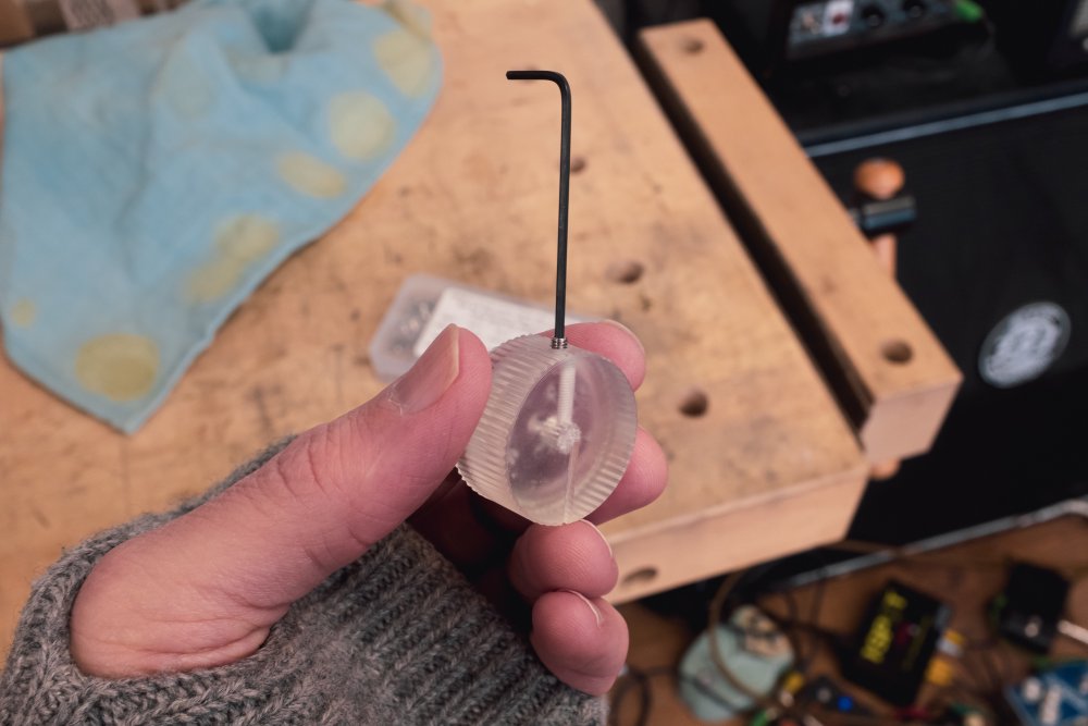
This is also a nice demonstration of refraction in action, as you can see from the way the shaft for the screw visible in the resin doesn’t line up with the grub screw I’m inserting there :) Yay physics!
The final step is to paint in the indicator line. Given this control will be over a reasonablhy dark bit of walnut wood, I went with white paint for this:
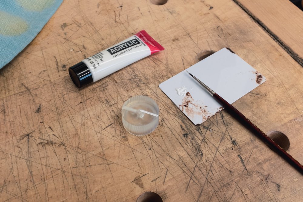
The paint will need a couple of coats, and so installation will have to wait until next week.
Picking a colour for verkstaden
Last week I wrote about the reshaping of my Verkstaden build, a change about which I’m still quite pleased:
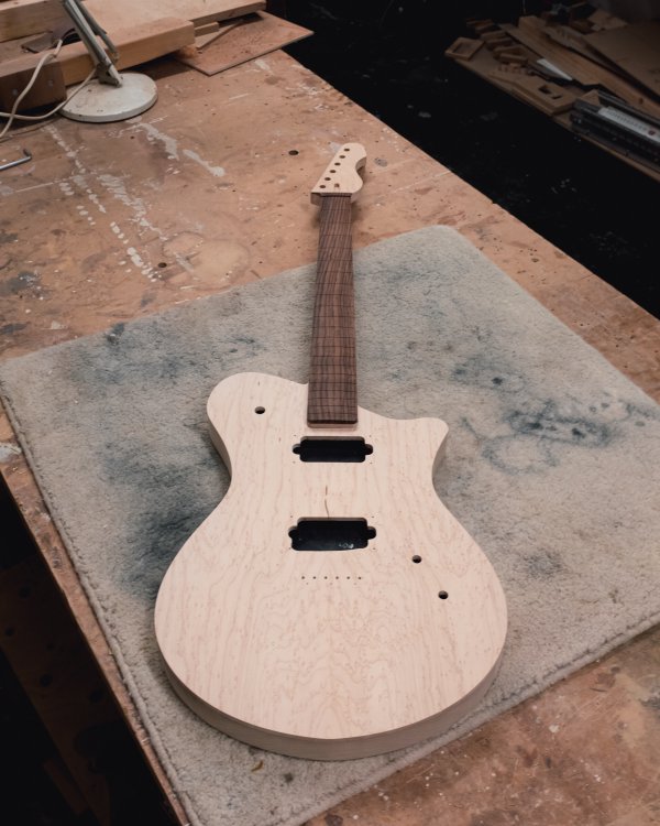
I’d been pondering how I finish this guitar. I certainly would like something colourful, as this is going to be a demo guitar, and needs to speak to my design preferences, and I like colour where I can get it, as hopefully my portfolio shows. But my last two builds have been quite muted, with Älgen has quite a refined set of colours due to how it’s come together, and the corvette was designed for someone who wanted more natural wood tones.
The body top on this guitar is a lovely birds-eye maple, and so I had a look around at examples of how other people have finished guitars in this fashion, and I decided I wanted it to have a yellowy/orangy look to it, as that is quite a light colour that lets the wood show through, but still has some pop to it.
It’s perhaps a little Les Paul, but I think I need to follow where the birds-eye maple staining takes me and theme everything else colour wise from that and the rosewood fretboard.
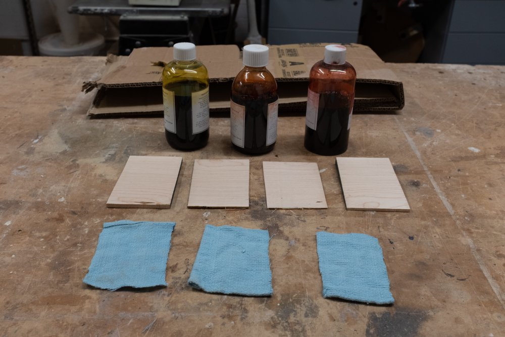
Obviously, this being me, I am tempted to make this more complex and do a burst effect, with the main background colour being yellow, and the edges being more of an orange. I’ve never done a burst before, and so I spent a chunk of time watching people do it on youtube to get the idea, and then have started to do some trial runs. For this, I took a bit of maple I had left over from another build, cut it up on the band-saw into 4 pieces, and then dug out my bottles of water-based stain:
I first applied yellow stain to all four pieces, and then added orange to half of one, red to half another, and then did the last one with orange first on 2/3rds and red over that 1/3rd, to give me more of a blend. Once I’d applied each overlay I’d use the rag I used for the original yellow stain to blend the edges.
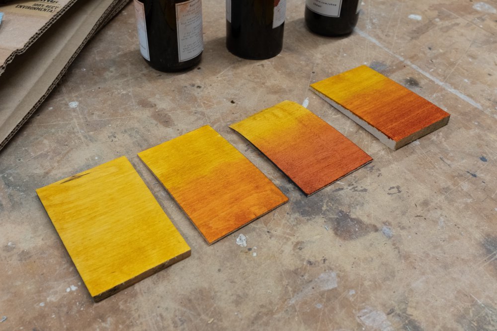
I did this at the close of the week, so they’ll need to dry and I’ll get to see next time I’m in the workshop how well the blending has worked.
Fitting a new power transformer in the practice amp
A few weeks back I mentioned how I wanted to get my old Fender Champ based practice amp I build back up running with its new power transformer. The old power transformer had burned out after a few years of daily use, and I was advised to fit a higher wattage transformer when I replaced it. The only downside of that is that the new transformer is also physically bigger.
When I last mentioned it I’d designed and made a template for the new transformer to let me drill new mounting holes and cut a new aperture for the bigger transformer, and this week I actually found time to put it to use:
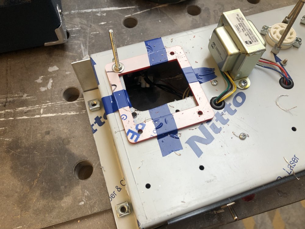
Not the prettiest setup, but it let me drill all the holes without the drill bit sliding about. I’d have expected the dents I made with the centre punch last time to have been enough, but I guess perhaps the drill bits in the maker space workshop (where I was doing this) weren’t the sharpest? I’m not sure, but the template solved the issue.
I then set about removing the rest of the material with a hack-saw. I’d have used a scroll-saw if I was doing this properly (which is how I cut the original hole), but given I already had some of an opening, and how fiddly it is to set up the scroll saw, and not wanting to strip the chassis down completely, I figured I’d go for the crude but practical option. That and a bit of rasp work got me to where I had a clean new hole, and I could fit the new transformer:
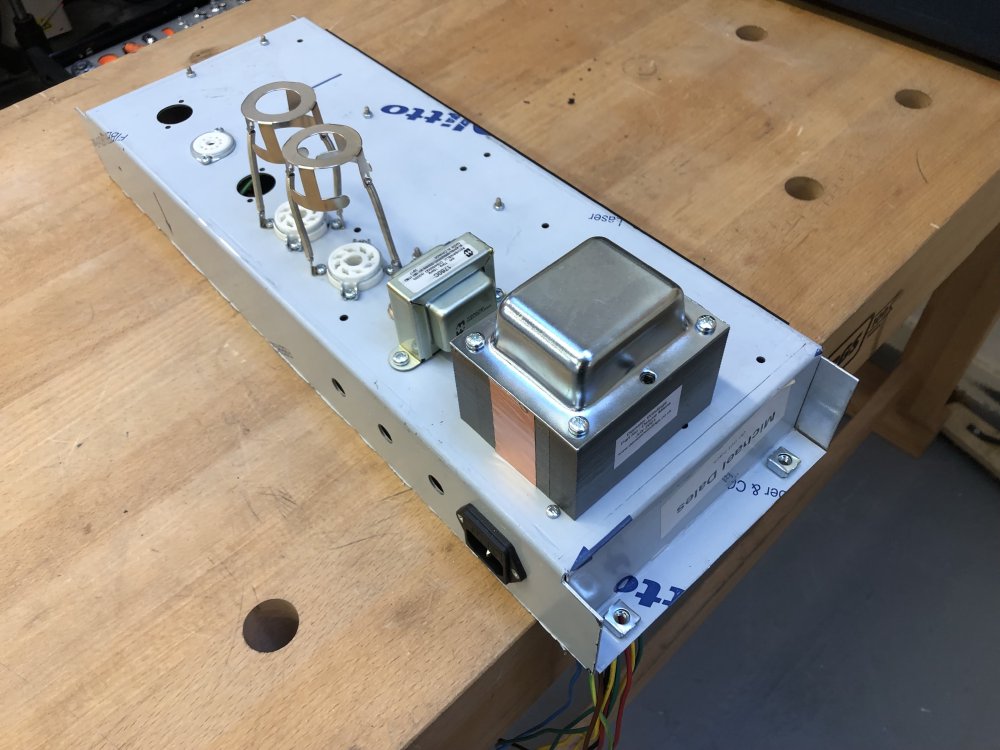
Looks neat from that side, less so from the other side, but it’s fitted, which is the main thing.
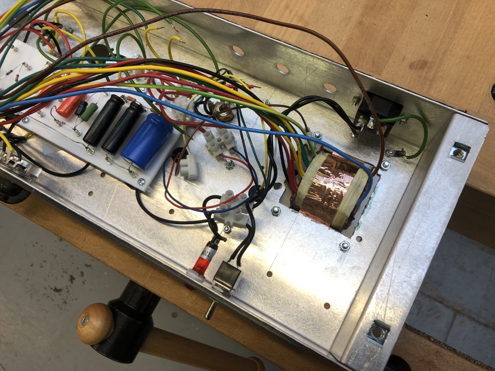
Having just done an excessive amount of exercise for me, in hacksawing metal into smaller and smaller triangles for 20 minutes, I opted to leave wiring in the transformer for a time when I was a bit more rested. When I originally wired the amp up I used terminal blocks to connect the transformer, as I didn’t want to commit to trimming and soldering the expensive part in until I knew it worked, and then never went back and undid that once it did. I suspect this time I’ll try do a neater job.
Assembling parts on the pickup winder
Not much progress on my little pickup winder project this week, other than a few minor steps. It’s hard to dedicate time to this over workshop time, but I try and find moments here and there just to keep nudging it forward.
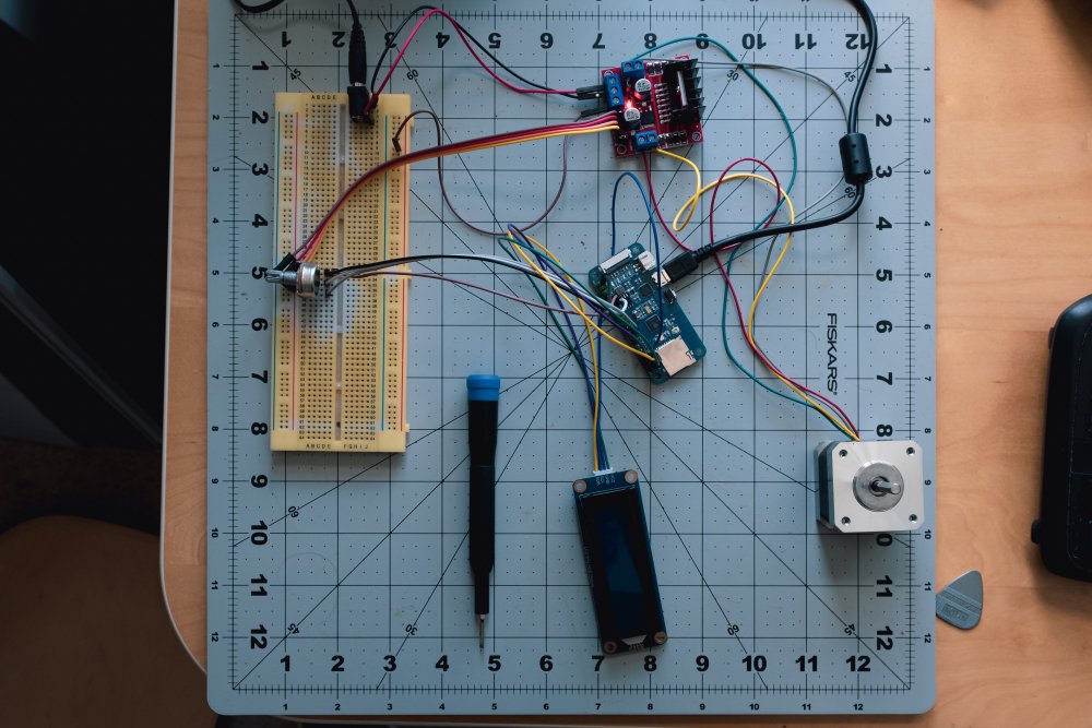
I did get a potentiometer wired in and being read by the ESP32 board, which I’ll use to control the RPM of the bobbin as it’s wound, and I did get the 12V power connected to the L289N motor driver board, and confirm that the 5V out from that, which I’ll eventually use to power everything else, works.