Älgen progress update
Published 23 Nov 2021
Tags: 3d printing, älgen, fusion 360, jigs
Although my attention has mostly been on finishing off the Corvette build so I can get that one shipped out, I did spend a bit of time de-risking my part wood/part 3D printed Älgen guitar design, and so it’s time for an update!
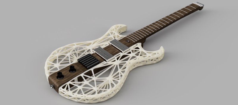
To recap briefly where we were, and then I can get onto what I’ve learned in my latest round of design experiments. The guitar is hopefully going to look a little like this when built - it’ll be made from a combination of a hand-made wooden core (old school construction) and then 3D printed wings for the main body (new school fabrication):
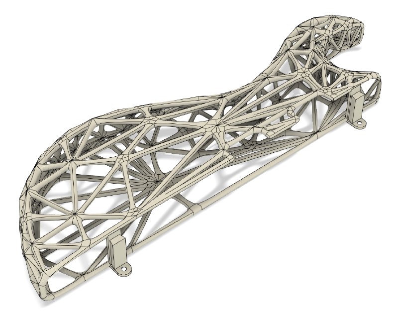
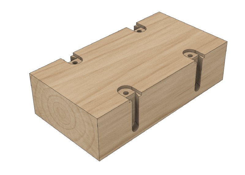
One of the interesting questions was always going to be how I joined the two worlds together. After too much procrastinating on this one, I decided to go for trying to use a dovetail joint, printing the plug on the wings:
and then the corresponding channel for it to sit in on the main body:
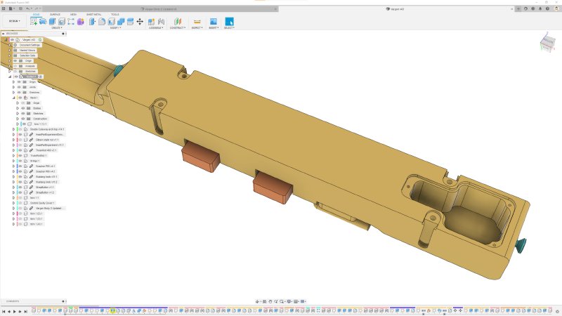
To make things more complicated you can see there is a plate on the 3D printed part to let me use a screw to fasten the part in place, which needs a corresponding recess cut for it to ensure everything is flush.
Whilst this all looks good in CAD, I had some uncertainty about the approach:
- How accurately would the 3D printed part printed? So if I have a dovetail router bit that’s a certain width, and I order a print to match, do I need to allow for any variance in the print dimensions?
- How can I cut the channels to be evenly spaced just using a hand router?
- How can I cut the recess for the plate to align up with the dovetail channel accurately?
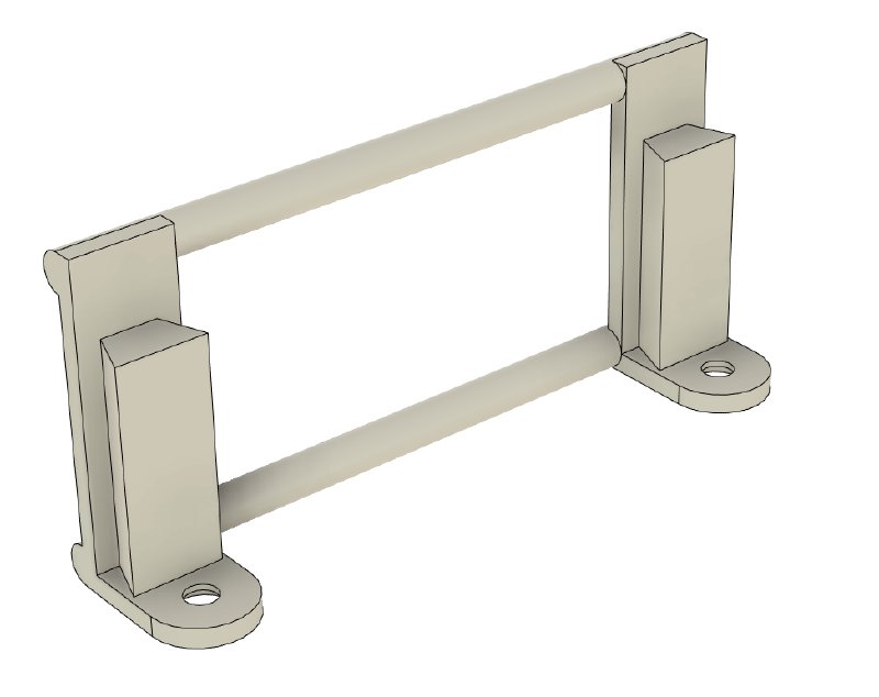
To try and answer these questions I designed a little experimental version of the joint on a smaller scale, which effectively lets me test just the joint rather than having to build an entire guitar to find out. I made a 3D printed part that has two of the mount posts full size, but much closer together to save on materials:
The idea being that I’ll mount them on a small bit of wood cut like thus:
Fromt this it’s a little more obvious that I need a jig that’ll let me use a router with a dovetail bit to cut down the sides, and then to swap that router bit for a regular end mill bit to cut the recess going into the top. So that’s two cutting actions per slot, one down the side and one along the top, and I need two slots per side at the right distance appart to match the 3D print. For that I designed a jig that would let me do this:
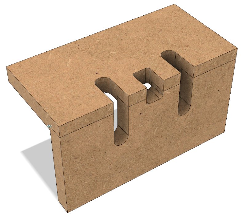
You can see the two slots, which are designed for a router with a guide collar on it rather than using a follow bit with a bearing. You’ll also see a weird smaller notch in the middle there: that’s a depth setting notch: for each direction I can just rest the router in that middle notch and push the bit down until it touches the material and then I know I’m at the right depth - at least in theory.
So, that ends the recap: I had a plan, but would it work in practice? Let’s see what happened!
First step was to make the jig, which I did using the CNC machine at the Cambridge makerspace:
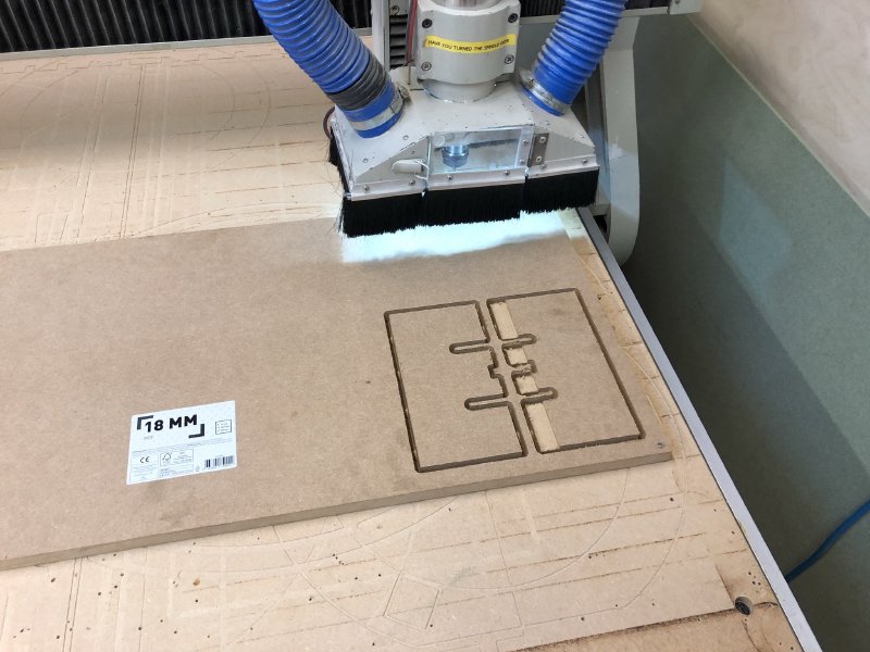
Normally I’d have used 12m MDF for a jig or template like this, but the guide collar on the router was too deep to let me use anything thinner, so 18mm it was.
Once glued into shape, I was ready to go:
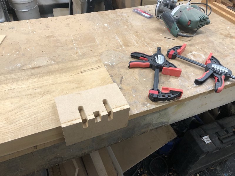
The first thing that I realised was that on my smaller version here I’d not really given any thought to how I was going to clamp it down whilst using it - doh! In the end I got away with just using one clamp at a time on the opposite end from where I was cutting (and adding the other clamp before removing the first one when switching ends). The wood I was testing on here was a bit of super-soft poplar, so I got away with this in a way I probably would not have had I been using a tougher wood that would have provided more resistence to being cut. Still, better to learn that lesson on my scale model than after I’ve made the full size jig.
As mentioned, to do this I was using a router with a guide collar on it, not something I’d used in anger before:
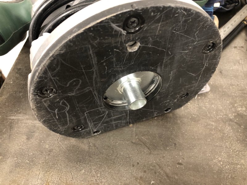
The collar is used in place of having a bearing on the bit itself, which I needed for this job as I couldn’t find a small dovetail bit that had a bearing on it. Getting a collar that was not too deep that it’d fit in a template but also wide enough that it’d fit the bit I need to use for the top plate was awkward, but I just got away with it. Despite not having an actual bearing, the collar works really quite well in this set up.
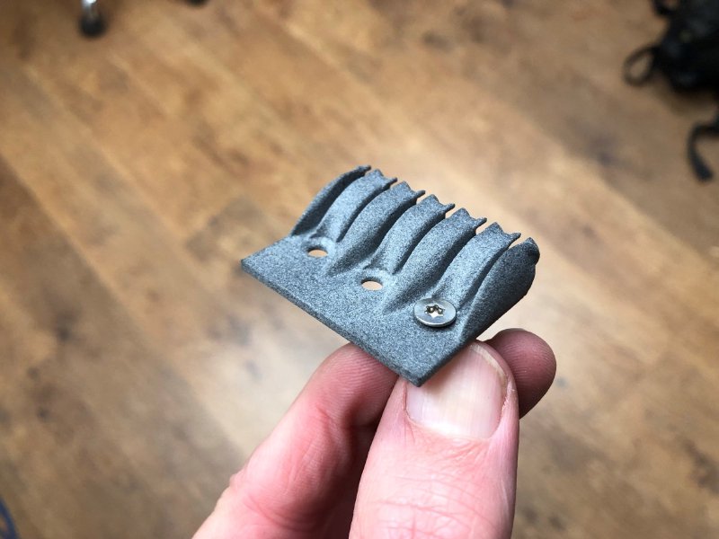
Much to my surprise, when it came time to cut things, everything just worked other than my clamping snafu. After a couple of test cuts to get used to working with the jig and the router collar, something I’d never actually used before, I had my test 3D print sat perfectly home:
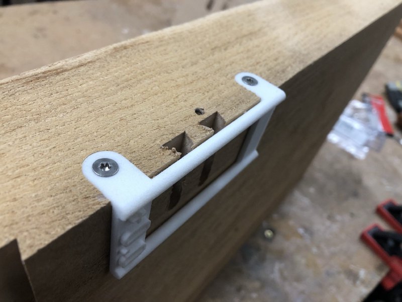
This is even the 0.0 mm offset version of my 3D print, which fit perfectly snug in the channels. As I noted in the last update on this guitar, I’d got several versions of the 3D printed part made, each a little thicker or thinner on the dovetail to allow for the 3D print not to quite be perfect on scale, a problem I’ve found with the ultimaker 3D printers I’ve used in the past, but hats off to Shapeways: the one that was submitted as the ideal size came out perfect, and I didn’t need the others! Don’t worry, they won’t go to waste - I have plans to use them for my dye testing in the near future.
To say I was happy at this point is an understatement: things don’t normally work out so well first time, and given how much I’d procrastinated over this trying to come up with different appraoches that might be easier, it was a relief to see this come together so well in the end. Even the depth stops on the jig worked perfectly, which I have to confess I was a bit skeptical about.
That’s not to say there’s nothing I’d change: I think the screw hole is probably a bit close to the channel now I see it in person, so I’ll probably add a bit more space there to avoid the risk of the wood splitting. I also think that, based on the rigidity of these smaller prints I’ll probably go for three mount posts rather than the two I have on the diagrams above. Whilst the posts here are held tight, there is a bit of give in the beams, so I think just having more support in the middle will help.
My other 3D printed test part that I made a while ago was the generatively designed headstock piece to anchor the strings, and that one will need another iteration, as I made the channels a little too narrow to allow for the extra material as the string is wrapped arouind the ball end of the string:
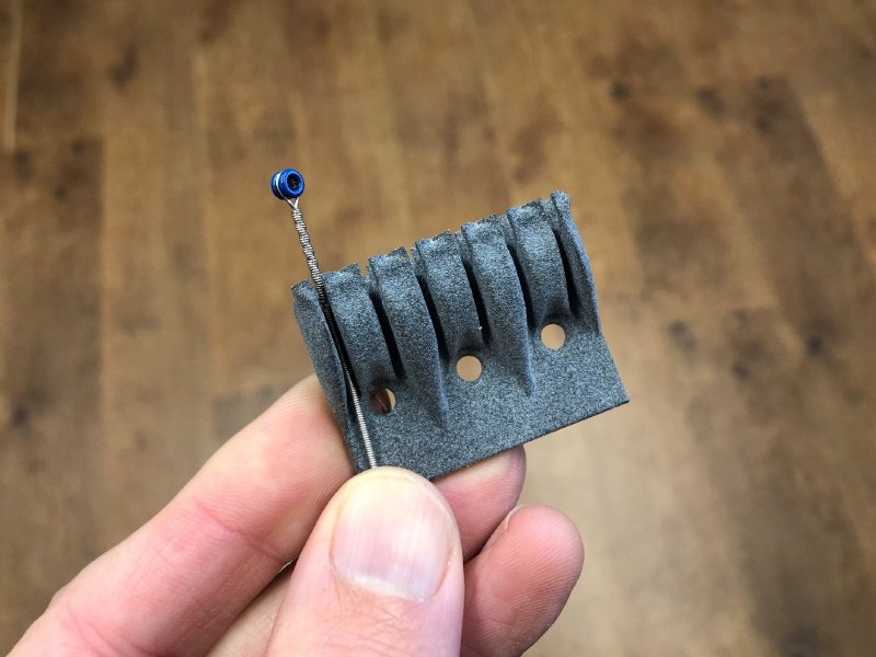
I’d made the channels 1.5 mm wide, but unfortunately for thicker strings that extra wound section at the end goes just over that:
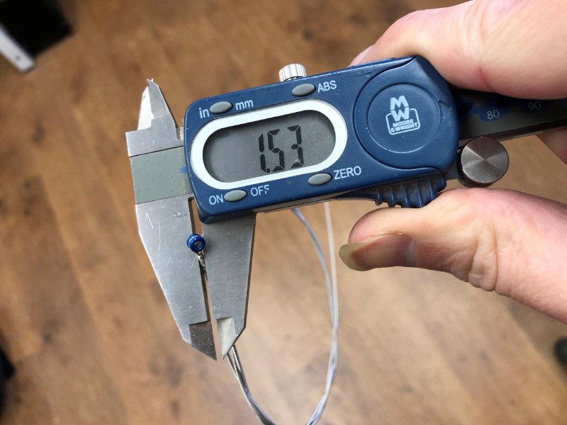
Intestingly enough, it did fit in some of the slots, because the generative design doesn’t need to fill up to the slot boundary with material: I just tell it it definitely can’t put material with the 1.5mm channel I’d defined, but that on the middle strings, I guess because the width of the material between slots is more, it didn’t need to up to the boundary I’d defined, whereas on the outer ones it really did need to fill the space as best it could.
Also when I did the original design I hadn’t finalised on the screws I would use for mounting the part, and the ones I nwo intend to use are a little bigger than I’d assumed back then, so I’ll need to update it for that also:
So I’ve now (literally just now) updated the constraints for the part and submitted it back to Autodesk’s cloud for another round of generative design. Once that comes back I’ll order another plastic print (assuming there’s no surprises during generation). And if that comes back okay, then it’ll be very exciting when I finally get to order an aluminium 3D print - my first metal print!
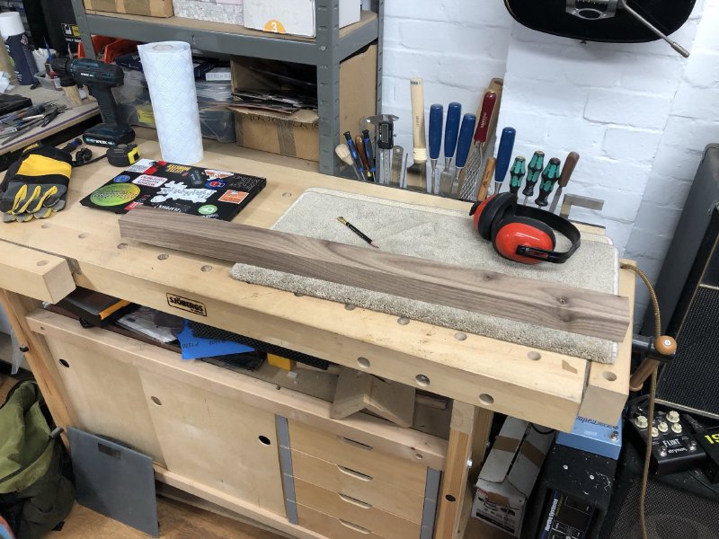
All this means I’ve reached an important milestone on the Älgen design: I’m confident enough that the overall design is going to work that I started prepping the wood:
This is one of a pair of walnut blanks I’ve got to let me prototype a full guitar. First this one went off to visit the bandsaw, to get it broadly down to the right size:
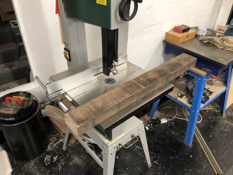
After three cuts there (one per axis) to get it into the rough ballpark for size, I then ran it through the thicknesser to get the width and depth to the right size:
The walnut looks really nice, so I’m quite excited about how this will look once done. There’s a couple of knots, which I’ll need to watch out for, but they’ll hopefully not present any issues based on where they’re located. I’ll most likely fill them with resin prior to finishing.
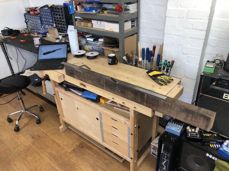
The blank looks a little short for a guitar when sat on my bench with no other reference, so after marking out all the main features with pencil, I put it beside Jamie’s old Telecaster that was in the workshop, and you can see (allowing for the fact that this guitar will be headless), it’s not actually that short:
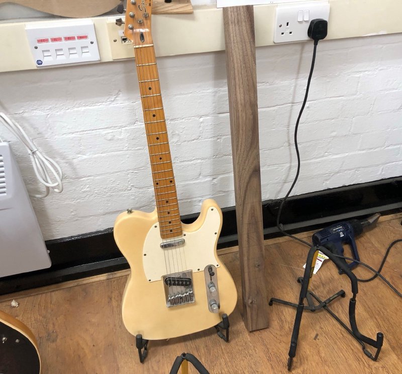
Marking things up in pencil already started to give me some insight to the real proportions of the guitar: I think I’ll need to tweak the position of the pickups to be further apart for instance now I’ve seen that at scale.
The next challenge is just working out how to cut the guitar out of this blank: where can I just go freehand with the bandsaw? Where will I need to use templates? What order do I need to do the cuts in such that I don’t make other ones harder? I find working through this process is much easier now I’m looking at the actual bit of wood than it is looking at a CAD model on a computer screen.
It’s great that things are finally starting to move on this guitar, and with The Corvette build nearly shipped, I can hopefully hit the ground running in the new year with just this guitar to focus on. Exciting times ahead!