End of year wrap up
Published 23 Dec 2021
Tags: 3d printing, älgen, fusion 360, generative design, shapeways, the corvette
I have to confess, this last few weeks as the year draws to a close have been a bit of a slog, and I’ve been perpetually putting off these notes until I have “just one more bit” done, so I felt like I had something interesting to write about. That took longer than I anticipated, but thankfully the looming end of year boundary was a good motivator to try get things ready for the new year, so finally here’s some updates!
Apologies for more than the regular number of typos and half finished sentences - I’m literally racing to get these finished when I should be helping out with xmas prep! But you’ll see that shipping rather than perfection is on theme this week, so I don’t feel too bad ;)
Before we look forward, a quick look back, as one thing I’ve done since the last update was I delivered the Corvette build to its owner, with a brief jaunt up to Scotland to hand it over. Between having to move workshop twice, the pandemic, and this being my first design from scratch it felt like it dragged on as a build, but I’m really pleased with how the design came out in the end:
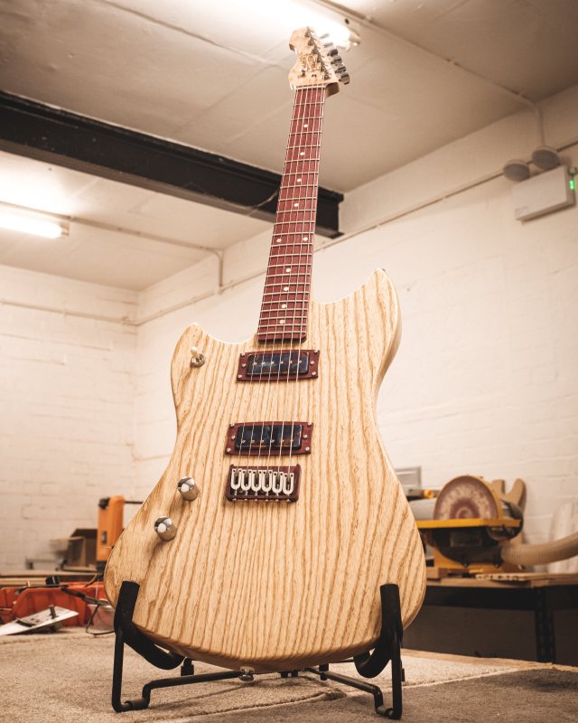
This is my first guitar that is 100% my own design, so as a builder it marks a nice boundary. Whilst I have no problems with building guitars that are based on other designs, it does feel like a nice way to indicate that I’ve at least learned something on the way being able to put my own spin on things, change the design to suit how I like to build things rather than say how Leo Fender wanted to mass produce them back in the 1950s. And despite there being a few curve balls along the way, I’m super pleased with how this build turned out in the end, with the final guitar looking both like I’d expected from my initial drawings and way better thanks to the tweaks that I made along the way as it became real. For fun, here’s the original design plan for the guitar:
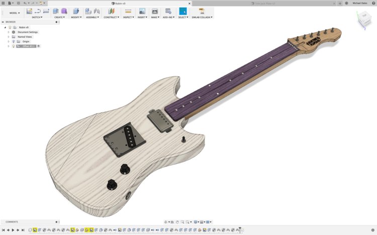
With this guitar I wanted to still lean on my existing experience building Fender style guitars, which is why it’s a solid body electric with a bolt on neck still, but at the same time I was able to fix things that frustrated me as both a builder and maintainer of guitars: all the electronics are accessed from the rear rather than having to remove the strings for instance - an idea obviously cribbed from a Les Paul, but it’s not about innovation for innovations sake here - I just went with ideas that would make the guitar easier to look after in the long run without compromising on playability.
Another change I went with was getting rid of the metal plate that is used to hold the neck on with a lot of bolt-on-neck style of guitars. This both freed me up to go for a more ergonomic shape, and makes it easier to string up the guitar before finishing, as those plates usually leave an imprint on the wood, which isn’t an issue with the ferrules.
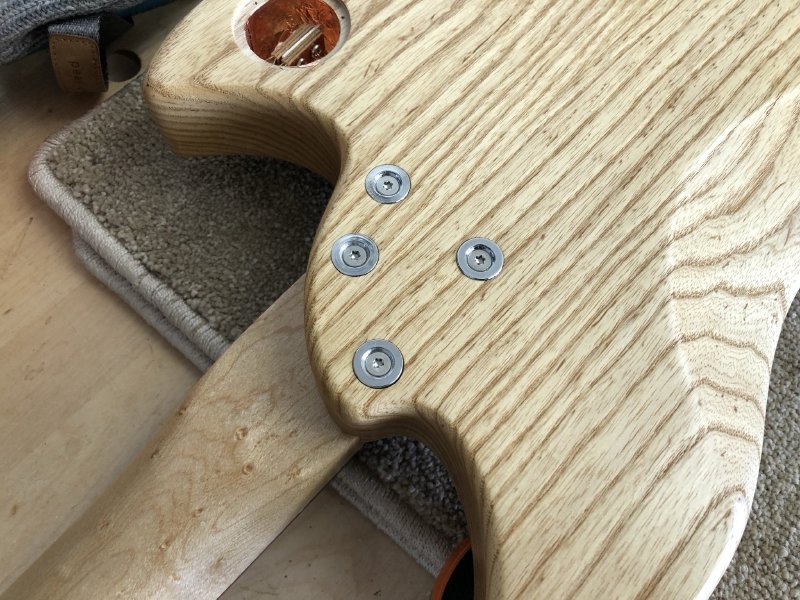
And (clearly most importantly) I think it looks way cool :)
Obviously there are things I learned as I went along that I’d tweak for the next time I build a Corvette model: I’d tweak how I shaped the cavities for the electronics to give more support for the covers, and I’d swap out the individual string ferrules for a single block design as individual string ferrule holes end up needing manual tweaking to get them just right and that’s a very labour intensive process. But that’s all part of learning as you go - nothing is ever perfect, and particularly not first time.
I definitely will at some point make more of these, so if you’re interested do get in touch. If nothing else I’ll need to make another one as a demo model, probably as and when I feel safe going to events again, but for now I’m going to just concentrate on my Älgen guitar design. Speaking of which…
The name for my new guitar design probably seems a bit weird (it’s Swedish for ’the moose’, and is pronounced a bit like ‘alien’ - both of which I feel describe its look quite well), but I have to confess that this month I assumed it was called something like ‘Mississippi Attestation’ as the process of dotting the ‘i’s and crossing the ‘t’s dragged on 🤪
My aim for this closing month of 2021 was just to get myself set up for the new year in the workshop by ensuring that I’d removed all the assumptions in the design that it’s easy to miss but can make a big difference in terms of buildability: do I know what screws will be used, and will they fit? Have I actually measured the parts (or got technical dimensions if I don’t yet have the part) and checked they’d fit?
Despite the pretty renders I keep posting, there was still quite a lot of this to do. I got out the calipers and measured the bridge and the spoked truss rod I had bought, and I made sure to find parts with technical drawings for those bits I’d not yet got.
At this stage some of these parts aren’t ideal; for example, someone give me guidance on the shortcomings with spoked truss rods for instance, but I’ve not had time to dig into this nor adjust my design so that I could use a regular truss rod. But a not-perfect guitar that gets built is better than an imaginary perfect guitar, so for now I just want to push on with what I have and I can refine things in future builds based on the first build - a lesson learned from The Corvette. I just really want to push forward in 2022 on building rather than design, as the building will teach me a bunch of where I need to tweak things anyway.
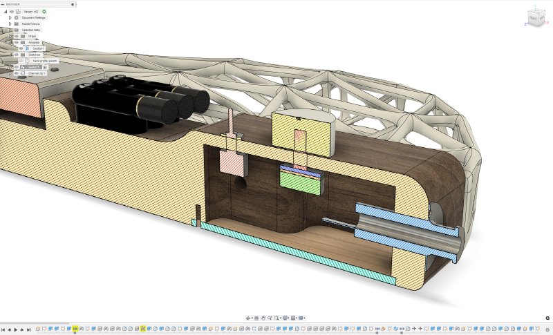
In a similar vein, gone is the tone control: I just have a single volume control, and a much smaller pickup selector switch than I had originally planned (but you may have noticed was entirely missing on earlier renders). This is an obvious compromise forced by space constraints (as you can see above), but of the three controls on a typical guitar (volume, pickup selector, tone) I know which one I use the least, so for now it’s down to two controls that are easily accessed. I’d rather have fewer, well placed controls than more controls that are fiddly to use. Again, I have to keep reminding myself that this is just a prototype, so I can change it later if people find it a limitation. Right now it’s just more important to have a decision on bits like this so I can confirm they will work at all, and move on.
There’s a story, most likely apocryphal, that if you know your AutoCAD versions, you can tell which version was used to generate the latticed roof at the (no longer) new King’s Cross rail station in London: as AutoCAD gets tweaks and updates how it generate structures will evolve, so if you use any automatic generation tools what you got in version A won’t be the same for version B with the same inputs.
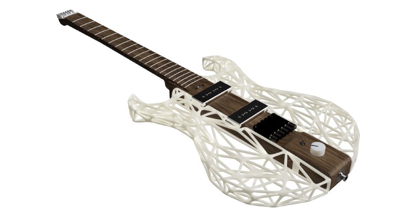
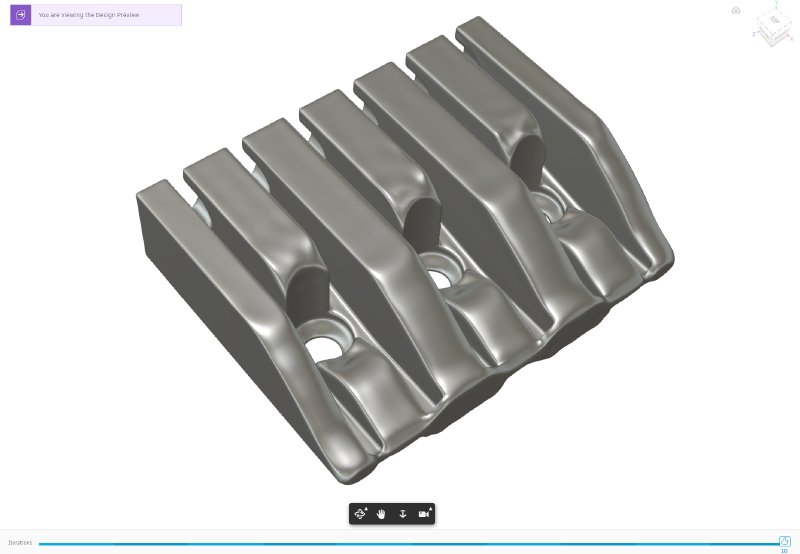
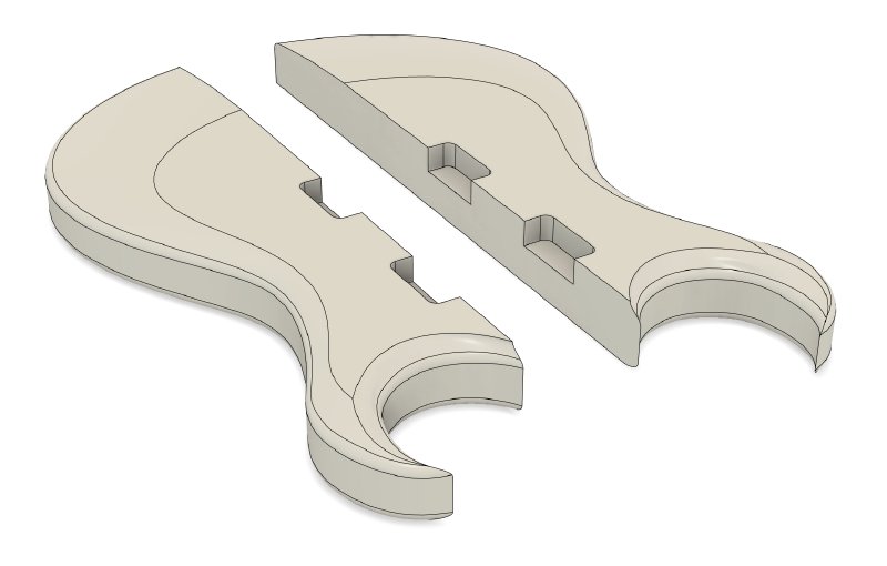
Frustratingly I hit this using the generative design feature in Fusion 360, as I came to update the part I’d designed earlier in the year to hold the strings on the shortened headstock of this guitar. The original design looked like this:
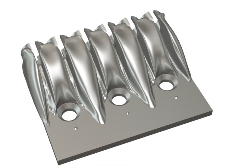
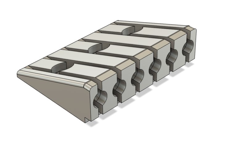
I quite liked this design, as it compliments the organic lattice work of the body. My first version that I designed myself just looked like a series of wedges, and didn’t fit the design very well at all.
(this picture is from the other side compared to the one above it - apologies, that’s all I had to hand when rushing to get these notes out).
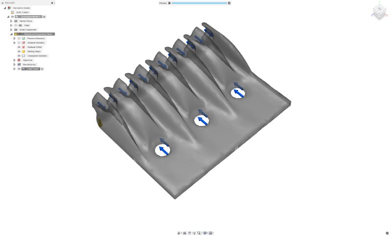
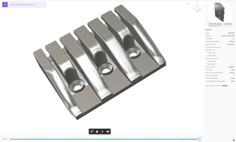
As discussed in the last update, I had to tweak this design to make the channels a fraction wider, because I’d not allowed for how the strings are wrapped over themselves at the ball end. This all went well, and when I ran the preview mode before submitting the model to Fusion 360’s generative design cloud, I got a design that looked very similar to my original run:
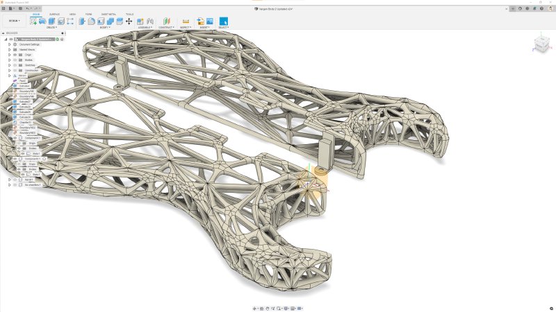
But when I submitted the design to Autodesk for proper generative design, the results that came back ended up looking very different:
Ew.
Now, in fairness I had made the channels for the strings slightly wider, so I’d expect the generative design to beef up the material in the walls a bit to compensate, but the generated result has a lot more material on it than the preview had, and indeed it now had so much material added it went over the bounds of where both the strings need to be and where the piece would attach to the guitar, so the generated design is unusable.
I went back and tweaked my model a bit and added some more constraints as to where it could put material, and what came back was better, though still nowhere near as nice as my original design:
Even more frustratingly, even if I wanted to use this design, every time I asked Fusion 360 to export it, it just said “I’ll think about it” and then never did. 🤦♀️ I’ve had better days :)
Had I liked this design I’d have gone and hassled Autodesk support as to what was going on, particularly as each generative run costs £40. But given I wasn’t that taken with what the generative design was now producing, and with my limited knowledge of how it works I worried I was just throwing good money after bad based on my own lack of understanding, I decided to just cut my losses and see if I could manually come up with a design that was more akin to what I originally got.
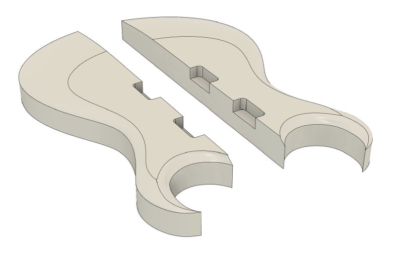
The way generative design works under the hood (as I understand it) is that it fills the design area with lots of material, runs a stress analysis, sees where there is no load on the material, removes a bit of that, then repeats until it either meets a target strength (e.g., this part should handle up to twice the expected load) or it gets bored. So I tried to take a similar approach, by manually running a stress analysis on the part in Fusion 360 (which I can do locally on my own machine, so I don’t need to pay Autodesk each time I do it) and tweaking it as I balanced the material vs load.
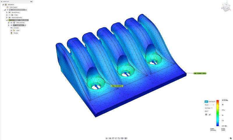
This enabled me to come up with a part that met the similar stress analysis as what I was specifying for generative design, but with a much nicer visual output than Fusion 360 was giving me now, more akin to the nice swoops of the original generative design.
I should caveat all this by pointing out I’m not a trained structural engineer: I’m messing around with things that I don’t really have a right to be doing so, and thus it’s probably just I’m holding it wrong. But I just had so much luck the first time around it was frustrating when the wheels came off the second time.
Still, I’m quite happy with how the manually designed one looks, so I’ve ordered a plastic 3D print of this part to let me test again for size before I go to the expense of printing it in aluminium for a real life stress test!
But I guess the real lesson here is if you use Fusion 360’s generative design and get something you like, try and do any iterations on tha t design as soon as you can so that if Autodesk decide to tweak how their generative algorithms work then you’re not left with a radically different output for a similar input - with Fusion 360 you really have no control over versioning of your tools, which means you’re beholden to their whims on this sort of thing.
Another part of doing all the Is and Ts was making the templates and jigs I’ll need. I had hoped to use fewer templates and more traditional hand tools on this build, but again I decided to try and not do my usual trick of innovating on too many fronts and just stick with techniques I’m familiar with. Thus, the neck shape will be made with a laser-cut template and a plunge router rather than a hand-plane (similar to how I did my cigar box guitar’s neck).
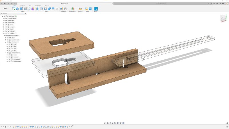
I also designed a larger of the jig I tested last month for cutting the channels needed to mount the 3D printed parts. One issue I hit with that first test was how to secure the jig to the material, so on this one I’ve used screws to let me let attach it to the neck, and the screws will go into the material that will be later removed for the pickups.
Doing these did bring home that whilst this guitar looks a lot like a traditional through-neck guitar build, it differs in one important aspect from most of those, in that the body section of the neck is wider than the fretboard (which is done to accommodate the bridge securely). This means I can’t use my usual technique of routing out the back of the neck from a template, gluing on the fretboard, and then trimming the fretboard to match. I suspect I’ll need to make the fretboard to size and then glue it on after all ready shaped and slotted. I have done this in the past, but try to avoid it as if you get the alignment even slightly wrong you’re left with quite a big problem to fix, but I know it can be done, so we’ll just have to “get good” as the kids say.
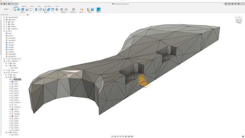
The final task was to remodel the 3D printed wings one last time. The process for generating the wings is quite fiddly in Fusion 360, as it’s a somewhat convoluted process to pull off, but the current iteration had two things I wanted to fix before I committed to getting them professionally 3D printed. Firstly, where the front and back transitioned to the sides, particularly on the tight sweep of the horn near the fretboard, there were a lot of small triangles that blended into a solid mess in places, despite my trying to manually de-densify this, as you can see here:
After trying another pass just manually removing vertices to get it less dense and going slightly mad in the process, I realised that I need to go back to the original model and remove these additional triangles at source. Before I go through the process of turning a shape into a mesh like this (as documented back in this post), I start with this body:
The problem is that the triangles are all caused by the rounded over edge that runs around the body. Now on a wooden body build I want those there, as it adds to the comfort of the build, but I realised that the mesh is already somewhat rounded (it’s made from round pipes!), and so I could just remove those. That gives me this:
Which then when run through the meshification process (and I wonder why people don’t normally let me name things) I get to this:
It’s still a little dense in places, but much nicer I think in terms of visually being a mesh all over.
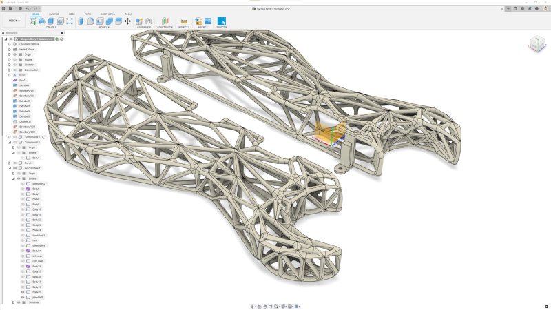
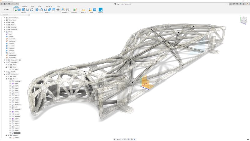
The other thing I changed you can also spot in that second diagram: I put in some extra struts between the front and the back of the body to hopefully give it some more rigidity. If you follow the original set of instructions I posted, then you end up with a mesh that just follows the outside of the original body. That’s because you take your body, turn it into a surface of triangles, and just make pipes along those edges, but there’s no way in that to get internal vertices.
To do that, I had to insert another step to my process. So after I’ve converted the body to a rough mesh like this:
I added a sketch where I then drew lines between points on the mesh. Normally Fusion 360 sketches are seen as 2D diagrams, but you can in fact draw lines quite happily between any point on a 3D model. So here I selected a few points between the front and the back an added some extra vertices, as you can kinda see here in black, if you squint:

Then when I went to generate the pipes I selected not just the body edges, but also the sketch lines I made, and the pipe tool will happily with with the lot of them. Which, again, you can kinda see here if you squint:
With that done, and after much checking that the measurements on the dovetail sections matches those on my test pieces from last month (they didn’t to start with, so glad I caught that in review) I finally sent the body off to Shapeways for printing!
I very much hope these are right, or (as Adan pointed out) at least close enough to right that I can work around whatever I got wrong, as getting prints done at this scale are not cheap :) But it’s at least done, so that represents another major milestone on getting this build to reality.
And there we leave 2021, which has been a rough year on the guitar build front, but with one guitar delivered, and the next one leaving the design stage, rather than dwell on what I could have done better in 2021, I’m going to just concentrate on looking forward to building some more interesting guitars in 2022!
Best wishes for the holiday season and the new year, I hope you’ll join me for more updates next year!