A return to the shop
Published 2 May 2022
Tags: 3D printing, älgen, fusion 360, jigs, laser-cutting, palm router, templates
It’s time for some catch up posts once more. I had to take a hiatus from the workshop unfortunately in February and March, as life got in the way and it seemed best to just step back from guitar building whilst I got back on top of things. It’s always frustrating having to put something on hold that you enjoy, but I find, when feasible, it’s best to do a few things well rather than lots of things poorly - and given I had no client deadlines on the guitars right now, it was easiest to pause the guitar builds whilst I attended to other things.
So, here we are, trying to remember what was going on when last we picked up our tools. It’ll take a few posts to catch us up to date, but let’s get started with what happened when I was last in the shop in January, and take it from there.
The last time we saw the Älgen guitar I’d just roughly shaped the body and was ready to make the mounts for the 3D printed wings:

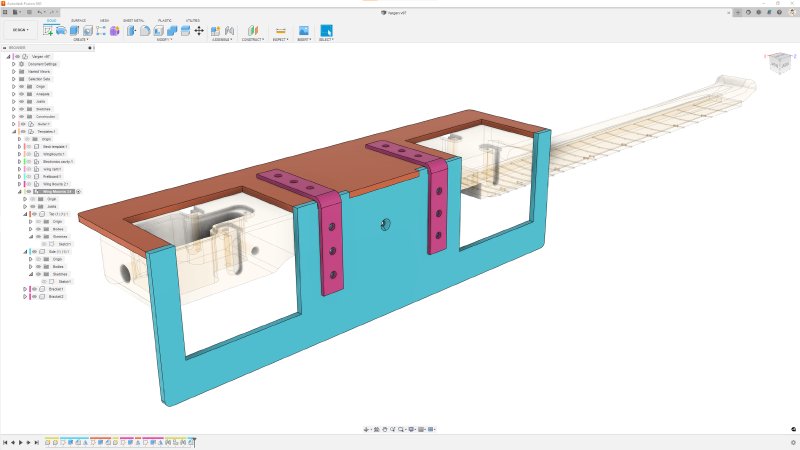
Although all the bits are placed in close proximity in the above photo, the three parts are not yet joined there. To do that I needed to cut some mounting channels in the central wooden part to pair with the dovetail-and-plate mounting that is on the 3D printed parts. This CAD drawing shows the mounts on the 3D printed parts (white does not photograph well when trying to show detail like this…):

To let me mount these on the wooden core, then plan is to cut a pair of dovetail channels into each side of the guitar for the mountings to slide into, and then there will also be a recessed area for the plate on the back at the end of each channel, so that the plate doesn’t protrude, keeping the back of the guitar nice and flat.
To make the channel and the recess using a router will require two cuts that are perfectly aligned other, but cut perpendicular to each other. To achieve this I made a somewhat complicated jig, which I documented in a previous post: this jig is designed to let me user a plunge router to do each cut, just with a different bit: first a dovetail bit and then a standard end mill bit for the plate recess.
At the end of the last set of notes, I’d just made the jig on the CNC router and was getting ready to use it. This is the jig in place ready to use, and I’ve tried to scribble on it to indicate the cuts I need to make:

Normally for cutting shapes with a template using a plunge-router I’d use a router bit with a guide bearing on it, but I couldn’t find any dovetail bits that had a guide bearing, so instead I need to use this collar. The collar fits in the base of the router thus:

and will slide in the channels you can see on the jig above. Hopefully the setup makes some sort of sense :)
So, now that’s the set up. Let’s see how it works in practice.
It’s worth reiterating that before I got to this stage I had already done a test of this process which had been successful. Whilst I used smaller 3D prints to save costs, the mounts were the full size, and the router and bits I used were all the ones I went to use for the full guitar version. Thus, when I went to do the cuts for on the guitar body here, I was fairly confident that it’d all work okay.
Unfortunately, as you can see in the below picture, that wasn’t the case this time. Instead of two nicely aligned cuts, I got the two cuts being misaligned 🤦♀️

The most likely cause of this, and one that I’d been warned about by workshop-mate Jamie, is that the collar I used on the router was slightly off on one axis, meaning it was a little to the left when I did the top cut, and after rotating the work piece to do the second cut I was then a little off to the right (as you look at it - obviously I was off to the left both times :). Jamie’s warning was one of the reasons I’d made the test jig first, which had shown that the collar and router were aligned fine at the time.
So why didn’t I hit this in my tests? I suspect I was just lucky: the collar will fit into the router base in one of four orientations, and that first time I found a position with negligible offset. All positions look identical, but it would seem that isn’t the case, and the second time I came to use the same set up I hit the issue that was foretold and I’d thought I’d ruled out. In retrospect I should have checked it at the time, but I was so excited by my initial success it never occurred to me.
Fortunately for me I bought enough wood to make a second body on the assumption that something would go wrong with the first attempt to build this guitar, though I have to confess I had expected to make it further in the build than this early stage before having to start over!
In the above there’s a bunch of “most likely cause” and “I guess”, which tells you that I’ve not tried to debug my method and tried again. The obvious first step would be to try all the options for fitting the collar until I find one that is properly aligned and use a permanent marker to indicate which I should be using - assuming that it is just a simple offset on one axis with the collar.
But I’ve not done this, as truth be told, I was never that happy with the solution I was using, and this failure somewhat vindicated the nagging thoughts I had in my mind that I’d been ignoring for the sake of rushing on to make something cool.
The main problem is that the collar adds quite a lot of depth that I’d not initially considered. Because the router bit I need to use for the plate on the mount is an inch wide, I had to get a collar to allow for that, and it seems that as collars get wider, they also get deeper. I’m not sure why this is, but certainly it was true of all the ones I could find.
This has two downsides: everything was a bit more cumbersome than I had anticipated, with having to use deeper material to make the jig, but more importantly I was having to stretch how far I could clamp the bits into the router itself. Given I was making shallow, short cuts into fairly soft wood I felt I was still within the bounds of safety, but it really wasn’t ideal, and could be another source of error at some point.
So rather than do another run where I’d have all these same concerns in the back of my mind, I went back to the drawing board (aka, scrap paper and Fusion 360) and started from scratch. Well, not entirely from scratch: I already have sunk a lot of money into my 3D printed guitar parts, so I am now somewhat committed to the mounting method! But whilst I can’t change the mount method, there has to be a better way to make those channels.
Looking around the workshop at what other tools I could use, I happened across Jamie’s palm router, a DeWalt 26204:

I’d gone with the larger plunge-router initially because that’s what I always use when cutting templates, so it was a natural go-to for me. But it’s quite a large and bulky tool, meant for cutting way more material than I was trying to cut. An upshot of that size is that the base is very big, hence using a collar with the template rather than the base itself with a template. With this smaller palm-router the base is much narrower (103mm) and so I can feasibly make a template around that.
Even more interestingly, you can see that in its standard configuration as shown on the right of the above image, the base is just made from acrylic, and looks a lot like the templates I make. The standard template is narrow but deep (you can see it extends out towards the camera in the picture), and I wondered if I could make one that was a minimal square profile, given I’m only doing small cuts of 20 to 30mm on wood that isn’t that deep (42mm on the short side) to let me keep my template size more manageable.
DeWalt don’t provide a template for the base unfortunately, and so it was out with callipers and Fusion 360 to make my own template:

I suspect DeWalt don’t really intend for people to do this, given all the odd numbers here (they don’t even make sense in imperial either), but after a bit of trial and error (note the number of prints in the background) I got there. And then a trip to the laser cutter later and I had my own minimal-footprint version of the template:

The downside of laser cutting is that I can’t do countersinks for the mounting bolts when I cut the profile, so for that it’s a trip to the pillar-drill:

And then I get to mount it on the router ready to use:

At this point the question of alignment rears its ugly head again: how do I ensure that the template is mounted such that the router’s spindle is perfectly in the middle? Otherwise I’ve just traded one badly aligned router guidance system for another.
It turns out, and thanks to Jamie again for teaching me this, that DeWalt have considered that you’d want to change base plates (even if they don’t expect you to design your own, they do provide a spare incase the first gets damaged or worn out). They provide you with is a cone that mounts on the spindle, against which you press the plate as you tighten it to the base, which then forces it into alignment - simple but clever!

This cone keeps the plate true as you tighten it up:

So now I have a new cutting technique, which is much better suited to task at hand: it’s smaller in general, so easier to make such small cuts with compared to the plunge-router, and I don’t lose 15mm of router bit depth, I can get the collet right down to the same level as the material if I wish.
So, all that I need now is a new jig! I did a bunch of iterations on this, and I’ll save you all the in-betweens. but this is where I currently am on this:
Here I’m using two bits of material with slots that mate up with the new base I’ve made for the palm router, and I’m using a pair of right angle brackets to join them. I’m not in love with the right-angled bracket design, but I wasn’t sure how best to otherwise attach them. I could use some blocks of wood that I’ve cut to be true instead, which probably has a better chance to being perfectly right-angled than the brackets I bought at the hardware store, but I figured I’d start here and see now I get on. Because I’ve gone from having to CNC route the jig to laser cutting the jig I can more quickly iterate the design.

The other nice thing that comes from laser cutting is that I can make everything from a single sheet of material at the same time, and know that everything will fit together.
The one thing that I have lost here, which was a nice bit of design on the old jig (if I do say so myself) was that the old jig had nice depth stops slots to let me get the perfect depth for the router bit to cut. With the narrower material I just can’t do the same trick on this jig, so I suspect I’ll need to just CNC a stand alone depth template this time.
And that’s us up to date on my Älgen build: I’ll laser cut the template and assemble it next week, and then try it out on the new ruined body before using up my remaining body blank :)
I have some other bits I’ve done: I’m starting to build a new Corvette instance, and I’ve had some learnings about laser cutting complex files as part of my semi-regular gig cutting pick guards for my other workshop-mate Matt, but all that can wait for the next week notes, to encourage me to get back into the habit!