A week in the shop
Published 13 May 2019
No big achievements again his week, just a bunch of small things moved forward, and fewer of those due to it being a bank holiday in the UK, and my other half and I went to see the sea. Still, I made one complete thing this week, and moved some other things forward. Oh, and I also got my accounts for last year prepared for my accountant, which isn’t exciting, but is part of trying to run a business.
On to more interesting things: I started the week by having a go at manually thicknessing one of the neck blanks down to size. This particular bit of maple has some weird multi-directional grain going on, so no matter which way you attack it there’s risk of the surface tearing. I’d left it a good few millimetres short of my target thickness (19mm) when running it through the thicknesses as a result, and now that I have the new blade for my No 7 took about trying to get it down to size and clearing up the tearing already imparted by the thicknesser.
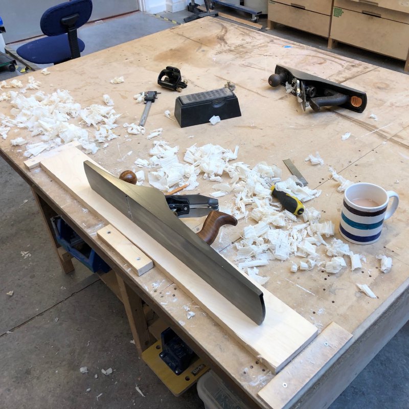
The new blade I ordered from Ray Iles really did make a difference, holding it’s edge much better than the one that came with this more affordable plane. I was getting nice long shavings in no time after giving the new blade a quick honing.
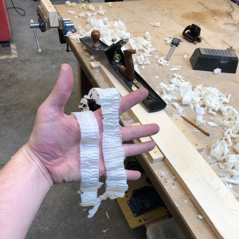
It took me a good few hours, but I got there in the end. I often make a bad joke about how Makespace is like a gym membership for the mind (with all the good and bad connotations that carries), but this day it felt just like a regular gym membership after all the manual labour for several hours. It really was an awkward bit of wood to work with due to the odd grain direction causing me to tear it again if not careful, but I got there in the end.
Next up for this bit of wood is to laser cut the template to let me turn this into a neck for a 25.5” scale length.
One of the reasons I wasn’t using the CNC Router for thicknessing was that the spindle was sufficiently out of alignment it was causing issues when used with the 2” facing off bit. At the end of the week Adrian and I had a look at fixing that.
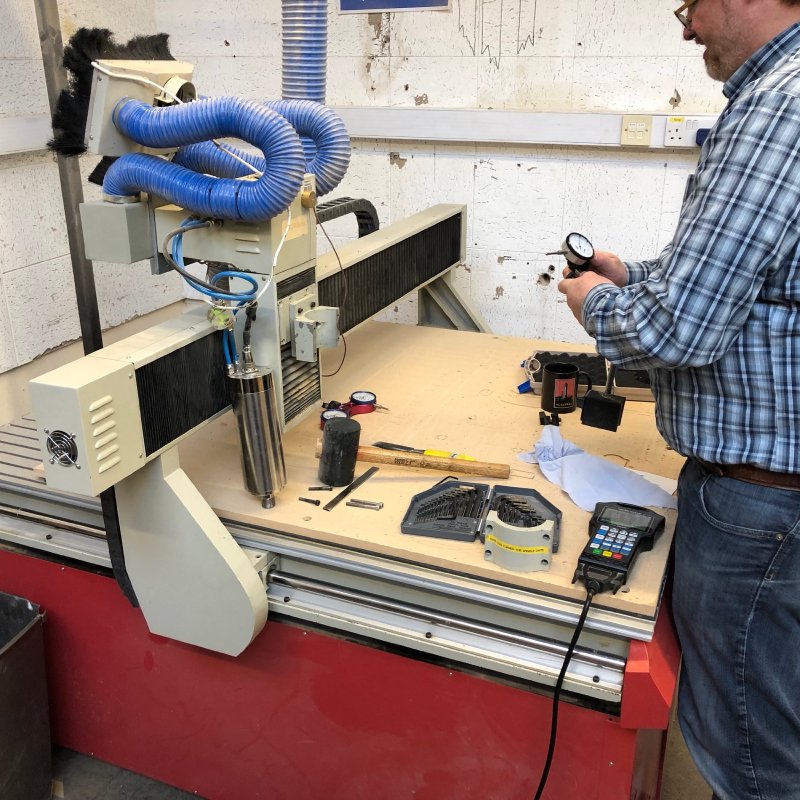
In the end the root cause was that over time some of the bolts holding the spindle in place had worked ever so slightly loose. Not enough to be obvious, but enough that if you gave the spindle a whack it’d move around. So we broke out the DTI (Dial Test Indicator) gauges and got it straightened back up and tightened properly, after which I was able to also re-level the bed which was well overdue.
If you’ve never seen a DTI gauge before (I hadn’t until I started being a carer for the CNC Router), it’s a very sensitive distance measuring gauge where a full 360˚ on the gauge is 1mm in travel, so you can use it to test for very small movements. Here we’d place it on the CNC Router spindle and move the spindle up and down to check for any horizontal movement between the top and the bottom.
I also spent a day taking the Masso CNC Router controller we ordered back at xmas and started getting that set up on the test rig we have (sorry, I forgot to take pictures of this one, perhaps next week). We ordered the Masso unit at the same time as the DM500 pendant controller we ended up running with, but since then the DM500 has shown itself to not be ideal for several reasons, so we’re back to looking for another replacement.
Initially I’d been put off the Masso as, whilst it doesn’t lack in features, at Makespace we are more concerned about simplicity and robustness in the face of confused users. However, having briefly played with the Masso now, it does look like it manages to pull off both of these. The main plus is that it also has an officially supported post-processor for Fusion 360, where as the DM500 has show itself to be unsafe when used with Fusion 360 generated tool paths using the basic GRBL post-processor.
This week the time I had was mostly spent just getting the Masso into our CNC Router test rig - checking the power requirements, levels for the switchers, etc. The test rig is just a series of motor controllers, motors, and physical switches that let us test a CNC Router controller without having to take apart and fit a unit to the actual CNC Router, which is a time expensive operation, particularly when you then have to put it back as you found it if said unit doesn’t pan out. I hope to have more to report on this next week.
I wrote a good while ago about how someone wanted me to make them a baritone, and they came back to me again keen to make it happen, so I had a call with them to get the full details of what they want, after which I made up a bill of materials and a rough CAD model so they can see what it would look like.
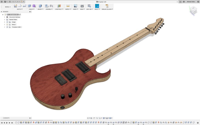
The design is based on the simplified version of my ambitious plans for 2018 that fell through, but I’m still very happy with the result. This let me make an estimate for them, and it would seem that they’re happy. Hopefully this will get properly commissioned in the next month or two.
Making the model required that I learn a new trick in Fusion 360. In Fusion there’s the fillet tool that lets you round over an edge. However, if your design consists of multiple bodies, the fillet tool won’t work if you want a nice even radius: it’ll only fillet a single body, so if you want to radius more than the depth of the top body it makes the fillet uneven. In the above guitar design the body cap (the red bit of wood on the top) is not as deep as the fillet I put on the edges typically (4mm vs 6mm), so I need to model that fillet going onto both the cap and the body underneath.
Here’s an example of what you get if you use the fillet tool to try do this sort of thing:
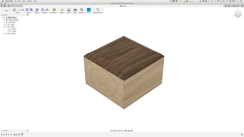
You can see that what should have been a nice even curve has been shortened to fit with the constraints of the cap, rather than crossing over to the second body. The trick it turns out is to make a sketch of the curve you want, and then use the sweep tool to use that sketch to create a cutting body along the path of the top surface:
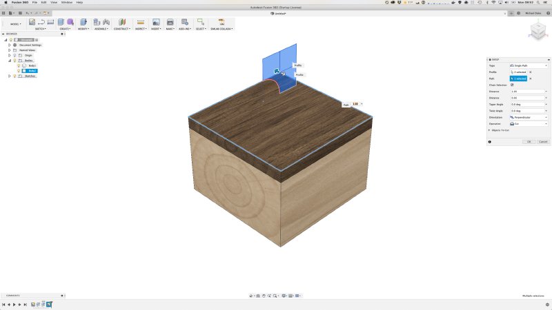
Once you apply this you get the effect you want:
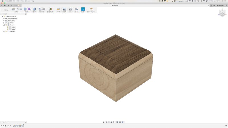
It’s not an ideal way of doing things, as selecting the path on a complex surface like a guitar top is fiddly to say the least, and I had to use several applications of this approach to get it right, but at least it is possible.
I’ve got a little preliminary feedback from the pedals I sent out last week to people. Seems that the old classic fuzz circuits are very sensitive to noise from the power supply.
I’d not spotted this in my testing as I have an isolated PSU on my pedalboard, and on the bench I have a wall wart of a reasonable quality. But both the people in the test cohort that are what I’d consider enthusiasts rather than professionals ran into this problem immediately unfortunately (which at least one solved by just going out and getting a better PSU, but it wasn’t my intention to cause my testers to have to go buy things!).
Most pedals I imagine these days do have a bit on the power input to protect the circuit and clean things up, but the older circuit I used does not, so any variance in the PSU will be passed on to your audio signal. This also covers if you have multiple pedals on one PSU and the other pedal is emitting noise over the ground or such. Something to remember for v2.
To wrap the week up, I made a quick thing for the workshop: a way to hold the scroll saw blades so that it’s both obvious where they are, and we can see when we’re running low on any particular blade type:
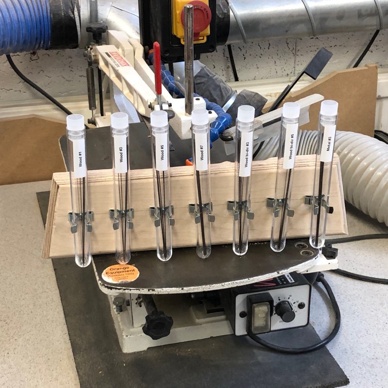
I think it was Toby who originally suggested we wanted something made with clear tubing and some caps, but that sounded like a lot of work when you can get ready made clear tubes of almost exactly the right size: chemistry lab test tubes! I bought some cheap plastic test tubes from eBay, some terry clips to hold them, and used a bit of wood from the scrap pile, and a little work later, voila!