A week in the shop
Published 28 Jan 2019
Following on from last week, I did more testing of the DM500 CNC Router controller to test its suitability for use in Makespace, and on the test rig we have it’s worked pretty well. It’s not without it’s own idiosyncrasies, but no worse than what we have (indeed probably fewer). Next step on that will be to get it tested on the actual CNC Router itself, to check that it works in situ. But given that’s effectively a day to do, it’s great being able to know the basic functionality works as should on our test harness.
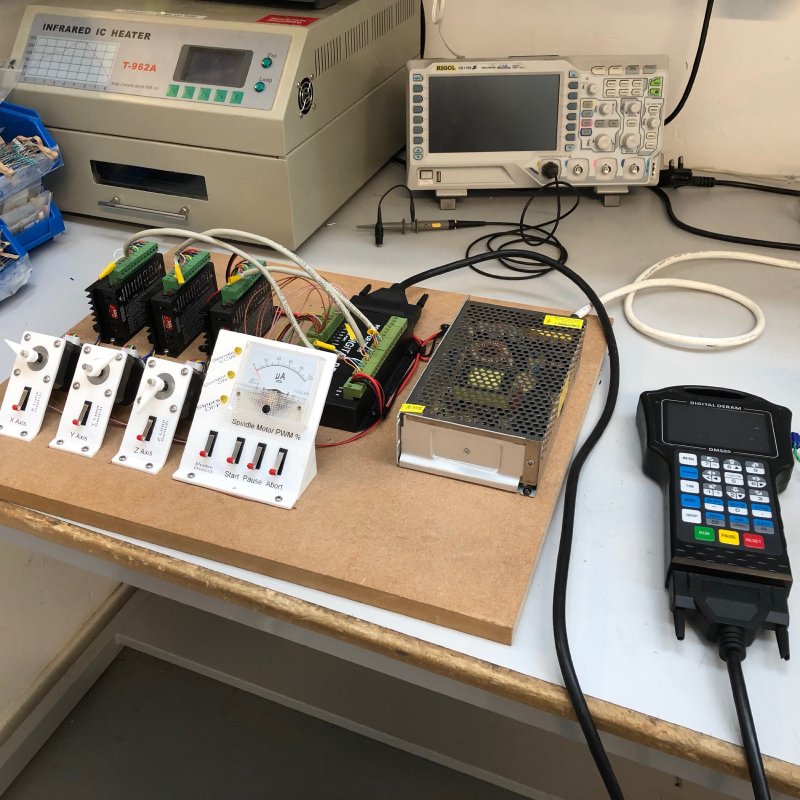
In terms of pros for this unit (beyond just working, which is not a bar all controllers appear to reach): the UI, whilst not amazing, is better than the current controller; it takes feeds speeds from the g-code itself (our current one can’t, so you have to set it manually each time), but you can also override it to be both slower and faster on the pendant (up to the configured safe maximum for the machine); and unlike the Grbl controllers we tried before it handles things like continuous jog properly and safely. On the down side, you can’t copy g-code onto the pendant before running it and it does incremental processing of the g-code itself. This has two consequences: it means you need to be careful that you don’t knock the USB stick that protrudes from the pendant whilst running your job, and the device doesn’t tell you if your g-code is going to exceed bounds until you get to that bit of the file. Not ideal, but then it actually otherwise works consistently and safely, which is surprisingly infrequent in this space we’ve found.
Given the downsides we still want to try the Masso controller unit we have also, but it’s great to have an option to swap out the current known bad controller.
I took a third go at making the pick guard for The Clydesdale guitar on the CNC router with the current controller: the first time it failed due to the CNC router misinterpreting some valid g-code, which I changed to workaround and then the second time it failed due to my double sided sticky tape failing to hold the material in place. This third time I ran the same known working g-code files on the CNC router, but made sure to screw down the centre of the pickups so they wouldn’t come free despite the double sided tape.
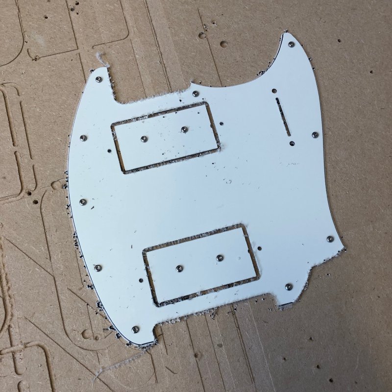
As you can see, third time’s a charm: the piece came out perfect thanks to the belt and braces method of securing the material (I’m still using double sided tape to ensure the PVC remains uniformly flat to the router bed). This means this week I can get started on the electronics for The Clydesdale - that’s all the manufacturing of bits complete!
The prototype offset has been sat to one side awaiting proper setup, which I’ve now completed. I’d been blocked on this waiting for my new set of nut files to be delivered, as I decided life was too short to keep using the cost saving trick of using nozzle cleaning files to cut the nuts. Proper nut files feel eye-wateringly expensive when compared with other tools you might get, particularly how briefly you use them (over a £100 for a full set), but I do say that they make the job so much easier: they’re both quicker to cut and more precise.
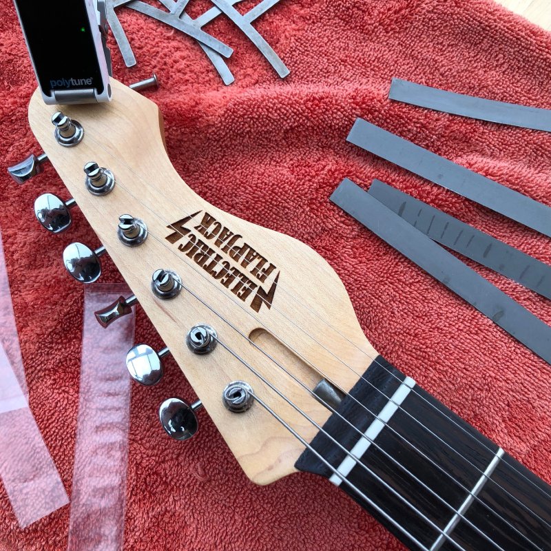
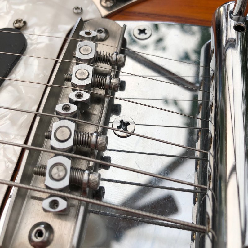
Thus in half an hour I had everything setup just as I wanted. This also involved setting the levels and intonation on the bridge. The Mastery bridge units are lovely, and much more secure than the standard bridge for this type of guitar, but they are a little more fiddly to set up.
Still, the guitar is now setup, and I just have to work out what it’ll cost to post so I can get it listed on reverb.
My plan had been to test out the new pedal board prototype by moving my entire pedal setup to the prototype for a bit, but I hit an embarrassing snag there. When I assembled my current pedalboard two years ago I used 3M Dual Lock, a sort of industrial strength advanced velcro, to stick the supply under my board. It turns out that dual lock is four times as strong as velcro, and as a result you should use less of it. Unfortunately I didn’t know this at the time, so I used lots of the stuff to ensure it never fell off. Unfortunately this means the bond is now so strong I can’t remove the power supply from my current board! Doh!
There’s things I could do to try remove them, but it’d leave either the pedal board and/or power supply a bit worse for wear, so I need to chalk this one up to experience, and when I sell my old pedal board it’ll be coming with a nice power supply already attached :)
I need to order a replacement, so if you have any recommendations for pedalboard power supplies, let me know. I’ve been happily using the Walrus Audio Aetos this last two years, but there’s been a couple of times I’ve hit limits of it’s current delivery for things like the OWL programmable pedal I have, so am shopping around for a slightly beefier replacement.
I spent a little time on my pedal switcher logic, and I finally got the MCP23017 IO Expanders working properly. Turns out that although those chips will work at the 3.3Vs from the regulator on the ESP32 micro-controller board I have, it can’t provide enough current. I moved everything to the USB 5V supply, and all is fine. Next step there is to try connecting the relays I have to the IO Expander. Once I have those working I’ll have all the major bits in place and can try a working prototype.
As a fun Saturday afternoon project, I finally made myself a fuzz pedal. I was going through my electronic bits box whilst putting together my pedal switcher circuit when I noticed I had just about the right parts to make the very simple circuit that is the original Fuzz Face design (albeit with silicon transistors rather than germanium). I didn’t have everything right, notably I was missing the right values for the input and output filter caps, but I found things close enough, and half an hour later I was playing through my own fuzz build.
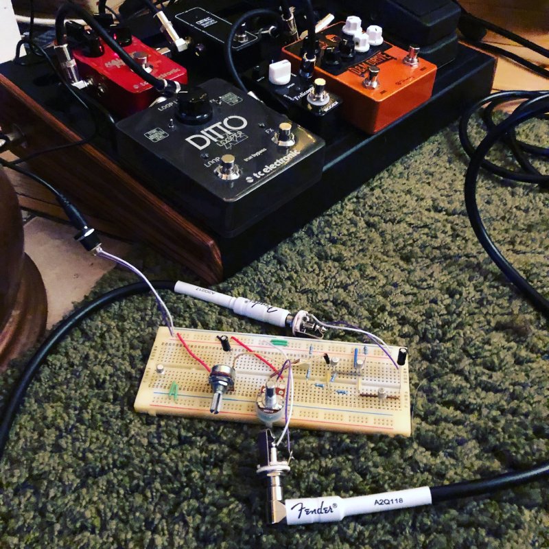
The sound is not perfect - I seem to have some power fade at points, though that could be due to my close-but-not-quite-right filter caps cutting out the wrong things - but it’s definitely recognisable as that early Satisfaction style fuzz sound. I did a little dive through the Makespace trove and now have some more bits to try and bring it closer to the original circuit next time I get a moment.
In the picture above you can see four transistors (the little silver cylinders on legs), but the circuit only uses two, so what are the other two doing?
They’re there for experimentation! I have two transistors of one particular type, and two of another, and I tried swapping them in and out for each other to see how it changed the sound. Whilst all combinations gave a fuzz type sound, I found I preferred the two that gave me a less harsh sound (using BC107s for both rather than any other combination of those and the BC108s I also had).
I actually bought a big-muff style fuzz pedal kit a while ago on the idea I’d make it, but in the end I never felt motivated to do so, as just copying an existing circuit for no other reason than to use it without change felt a bit pointless. But instead of using a PCB with a fixed configuration and making it on a breadboard like this lets me start to experiment and learn what impact each component has on the sound: I have a broad idea of what the circuit is meant to be doing, but that’s very different from being able to hear the impact of tweaking bits through your amplifier. I look forward to swapping out the filter caps in a similar fashion next time I get to play with it: when I found the extra caps I got not just the ones that are specified in the original circuit but others around the range to let me pick what I think sounds best.
And this is why there’s 1001 different pedals on the market: each one is subtly different and you have to find the right one that inspires you when used with your guitar and amplifier.