Workshop diary: trying a new approach to headstock shaping
Published 23 Feb 2025
Tags: 3d printing, jigs
In addition to the bass-guitar build I’ve been writing about, I’ve got a couple of electric-guitar necks I’m building at the same time. Both of these are regular (to me) 25.5" scale-length guitar necks, so in theory nothing new here. But I know that for the bass-guitar’s neck I’ll need to change things up, as some of the techniques I’ve used don’t scale up, and so I’m using these necks as a proving ground for some new approaches. This has the double advantage of it being easier to try out new techniques on something you’ve done before, so you’re not innovating on too many fronts, and it should leave me with an improved workflow that isn’t just suitable for the bass-guitar necks, but is generally better.
My approach to building a neck
I guess on disclaimer before I go on with this. In general I write these workshop progress reports so that others can learn from my mistakes or see a new technique they might use, but I feel this week we’re going into a weird territory this is due to the niche I find myself in: I don’t use a CNC-router, but I have access to some funky 3D-printing stuff, and so my workflow for building is probably starting to reflect this odd point in the building space I occupy :) But hopefully something in here will be of interest, and I do make mistakes for you to learn from along the way, I’m just not sure how applicable these learnings will be to most other builders out there!
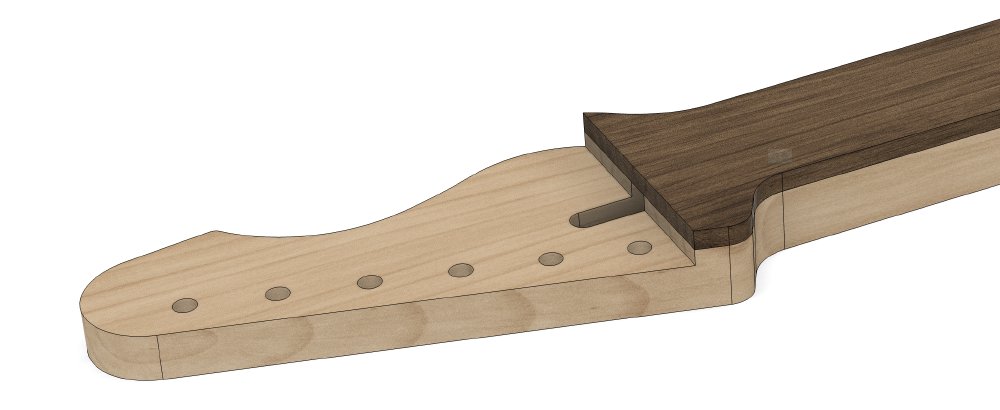
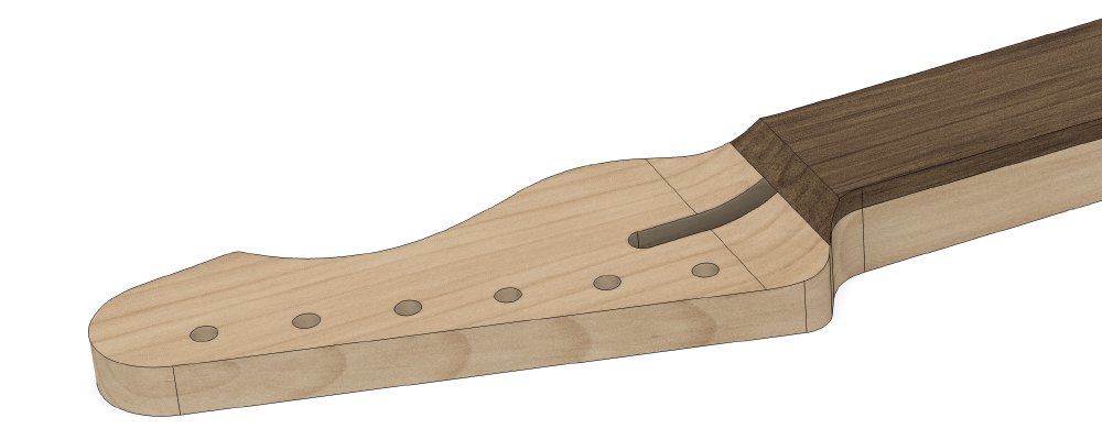
Whilst I said in the opening we’re talking about building guitar necks, we’re actually going to focus in this update on how the headstock is made. There’s two dominant styles of guitar headstock style: the flat style that you find on Fenders and others, and the angled style you find on Gibsons and others. There’s advantages and disadvantages to both, and as this will be a long post anyway I’ll skip that discussion for now, and just state that so far I’ve predominantly used the flat style, as that’s because it’s easier and less wasteful to build for someone with my experience and tooling. You can see an example of the sort of neck I build here:
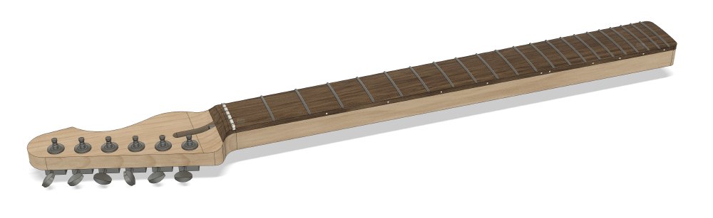
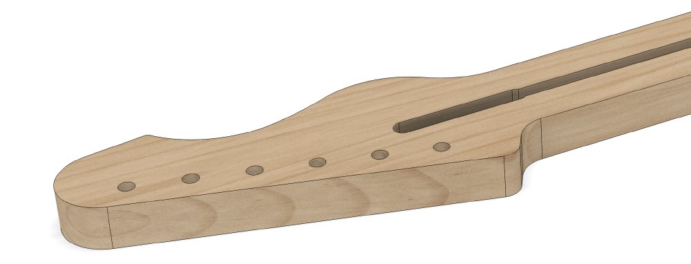
The first stages of my workflow are going to remain unchanged: using a template to cut the outer profile of the neck and the truss-rod channel, which you’ll see me do later. This gives us a flat profile of a guitar neck in wood like so:
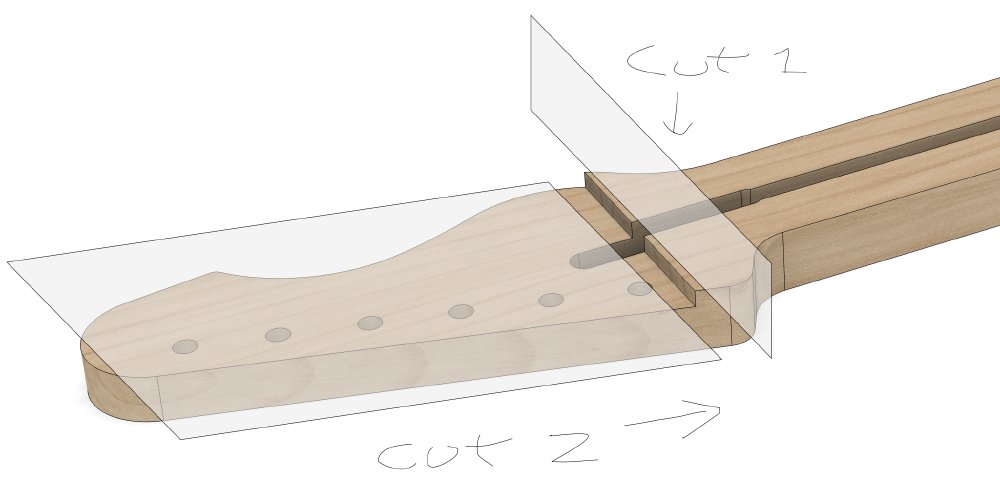
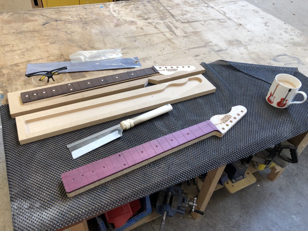
To start making the headstock to the right level, I then make two precision cuts with the band-saw, a shallow one perpendicular to the neck and one parallel to it along the face of the headstock just to remove the bulk of the material:
I then glue on the fretboard material and once the glue has dried I trim it to the profile of the neck:
And then finally I use a spindle-sander to round-out the transition:
Hopefully that gives you the general idea of my method.
The challenge is doing those cuts and the rounding on a piece of wood that doesn’t have nice edges parallel to the centreline for resting on the beds of machines like the band-saw and the spindle-sander. The sides of a guitar neck taper, it being thinner at the nut (for me 42 mm) than it is at the heel (for me 56 mm), which takes away the obvious contact point.
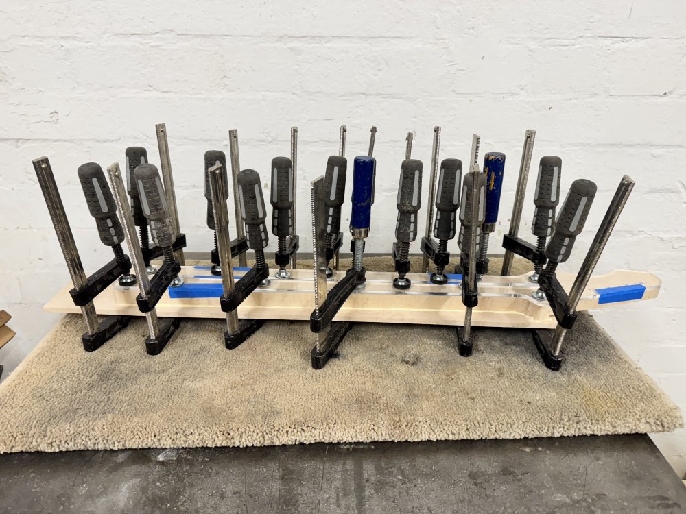
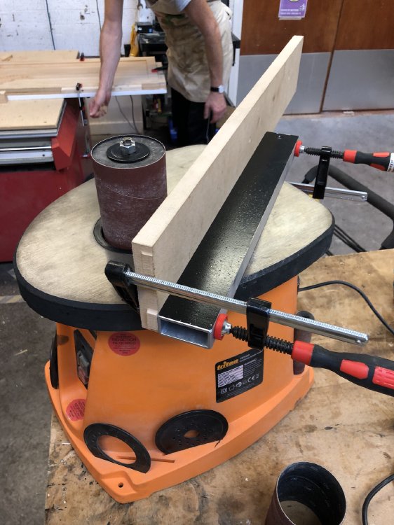
In the past I’ve solved this by using a full-neck-sized MDF jig made on the local maker-space’s CNC router to hold the neck for these operations. You can two such jigs in action in this picture from the archives:
These simple jigs, made from an 18 mm thick sheet of MDF, do get the job done, in that they provide me a straight edge that I can rest on the bed of both the band-saw and the spindle sander whilst I make these cuts, but they’re not ideal. Firstly they’re quite bulky to store for all the different variations I need, and most vexingly 18 mm is not deep enough to be super-stable on a spindle-sander without some extra material clamped to it. Again, from another old post:
Not particular proud of the above, but it did work after a fashion :)
Given this method isn’t optimal, and given how much bigger such a jig for the bass-guitar neck will be, I’ve decided I want a different solution. One that has the following properties:
- Indicates the various depths and positions I need to cut on it, including the rounding radius for the headstock transition.
- Is more stable on the spindle-sander without adhoc extra things being added to it.
- Is smaller than the entire size of the neck.
- Can be made without a CNC-router…
That last one is a Michael quirk obviously, as someone who is more at home with 3D-printing than CNC-routing these days, but it’s also a fun experiment. Making jigs out of wood usually involves some compromise due to the fact that say MDF comes in sheets of set thicknesses, and so I was interested in what I’d design if I was freed from those constraints. And if this trial works, then perhaps I’ll be emboldened to make more jigs this way and I can try making angled headstocks with scarf-joints by making it quicker and easier to build jigs.
Right, with the scene set, let’s take a look at progress on the guitar neck I’ve been building to try out a new approach!
From nothing to something
Mostly I’m including this early part of the neck build process here as it nicely emphasises what I discussed last time about using the router in different directions to avoid tear out. We’ll get to the jigs shortly!
To make this new neck I’m working on I started start with a 1" think plank of maple I thickness it down to 20 mm. By the time I’m finished the wood should be closer to 19mm thick, but it’ll get sanded and cleaned up as I work on the neck, so I thickness it a little over size. Once I have it the right thickness I attach a template with the profile of the neck and cut off most the excess using the band-saw, leaving a roughly ready necks:
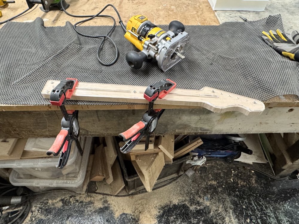
Once that’s done, I get the neck flush with the template using a hand-router. As described for the body I cut last time, this involves cutting from both sides so as to avoid tear-outs as the grain direction changes, but it’s a little easier as the neck is less deep than the body so I just need a single pass from both sides for the relevant sections.
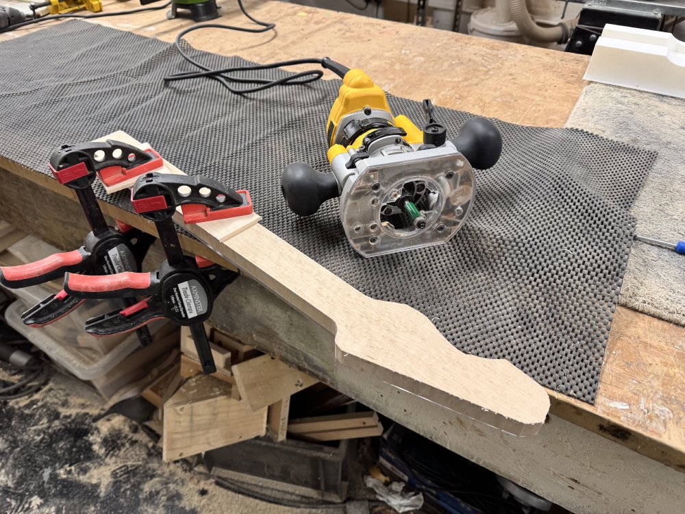
You can see in the two photos I’m using a different router bit: they’re the same diameter, but one has the follow bearing on the top, when the router is cutting from the side with the template on, and the other bit has the follow bearing at the end, for when I’ve had to flip the workpiece over and the template is now on the rear.
The new jig: Version 1
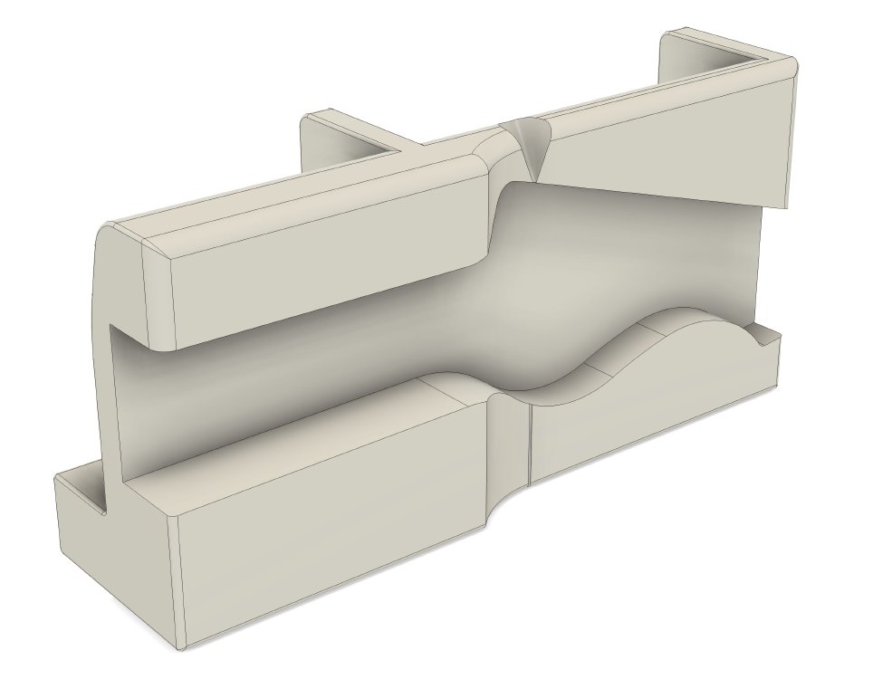
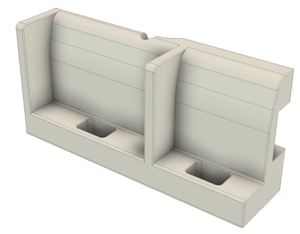
Here you can see the CAD model for my first attempt for a new jig to meet the above design brief:
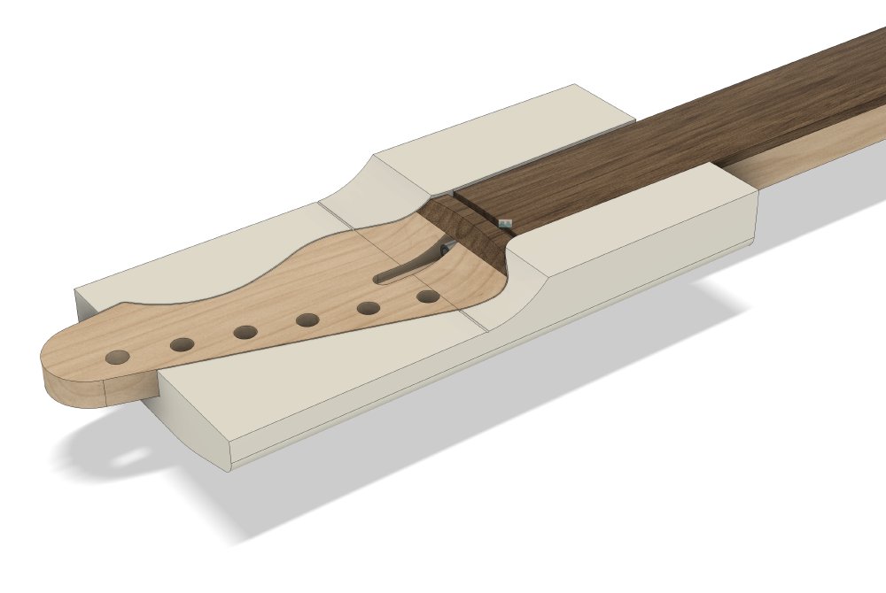
You can see how it has depth guides to let me how how deep to cut the headstock relative to the rest of the neck, and guides me where to spindle sand the transition to. It also has a clear line indicating that first perpendicular cut I’ll need to make when removing the face of the headstock. If we look at the rear, I’ve effectively built in that extra platform that I kludge in before, but just contoured a little to make it easier to hold on to:
It’s worth noting that the size of the jig is constrained by the size of the bed of the 3D-printer I’m using: the bed is 256x256 mm on the Bambu Carbon X1C. So whilst I did want a smaller jig as part of my motivation, the upper limit of what I can have is constrained for me. I was a little worried about balance whilst using the jig, which is why the jig doesn’t just centre on the headstock, I’ve also supported a section of the neck to try make natural instinct of it to tip over less. To be clear, it will tip over left to its own devices, but the more of the fretboard area of the neck I include the less I’ll have to fight that.
One printing session later:
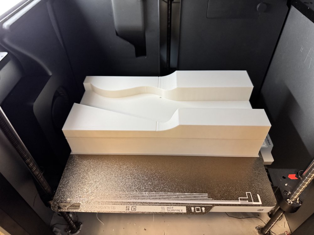
One thing that wasn’t shown in the CAD model was the supports that are added when printing: because of the flared out base on the rear the printed software has to put the supports there to make everything level. I printed it in this orientation so that there would be no support material in the areas where I’d place the guitar neck, thus ensuring smooth contact points that can’t damage the wood. To be fair to the Bambu printer I’m using and its software, I’ve generally found that supports come away cleanly, but that’s not always the case for some printers, which will leave raised material where the supports join, and I just didn’t want to take that risk.
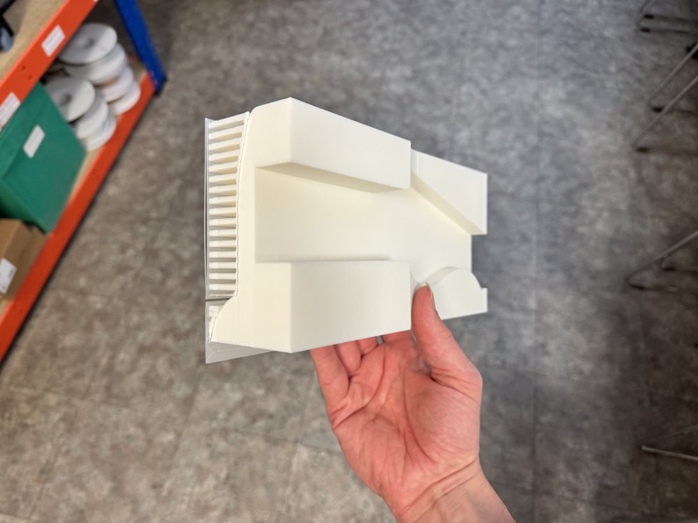
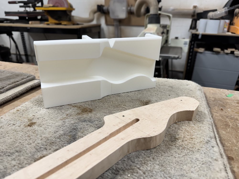
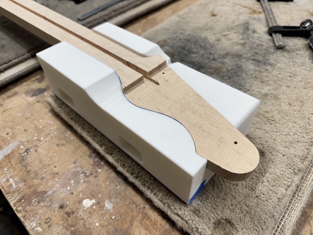
The supports did indeed come away clean, and it had a nice fit when I tested it with the neck in progress:
The print feels plenty sturdy for workshop abuse even at the default print settings. However, at this point I found two things I didn’t like about my new jig:
- Although the wider base did make it nice and stable for use with the spindle-sander, it was foolish of me to taper it to a narrow point as I did, as that means on the bandsaw we just have a very thing edge pressing against the fence 🤦🏼
- As mentioned, the first cut I’ll make is the one perpendicular to the headstock face, and because of the size and shape of the new jig, I found I couldn’t see the contact point of the blade when everything was in position to make the cut. Given how unwieldy this set up is anyway, that made me nervous to actually use this new jig.
So, whilst the idea I felt still had promise, this design wasn’t good enough, and so it was back to the drawing board (or the CADing computer I guess).
This is why 3D-printing was originally more commonly described as being a tool for “rapid-prototyping” (before the quality got to the point you’d actually use 3D-prints for production): having learned these lessons it didn’t take me long to re-spin my jig design and try again.
The new jig: Version 2
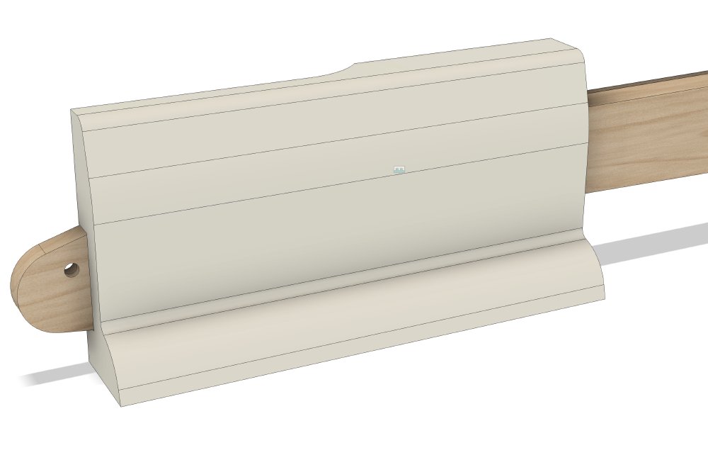
With all that in mind, I updated my design to address both of those problems. From the front:
And from the rear:
You can see that I’ve added a cut out on the top surface to allow me to see where the blade will make contact with the wood, and on the rear I’ve added some fins that will sit flush with the fence on the band-saw. I also added some holes speculatively (which is a fancy way of saying I didn’t bother measuring things like I should) should I want to use some clamps with the jig.
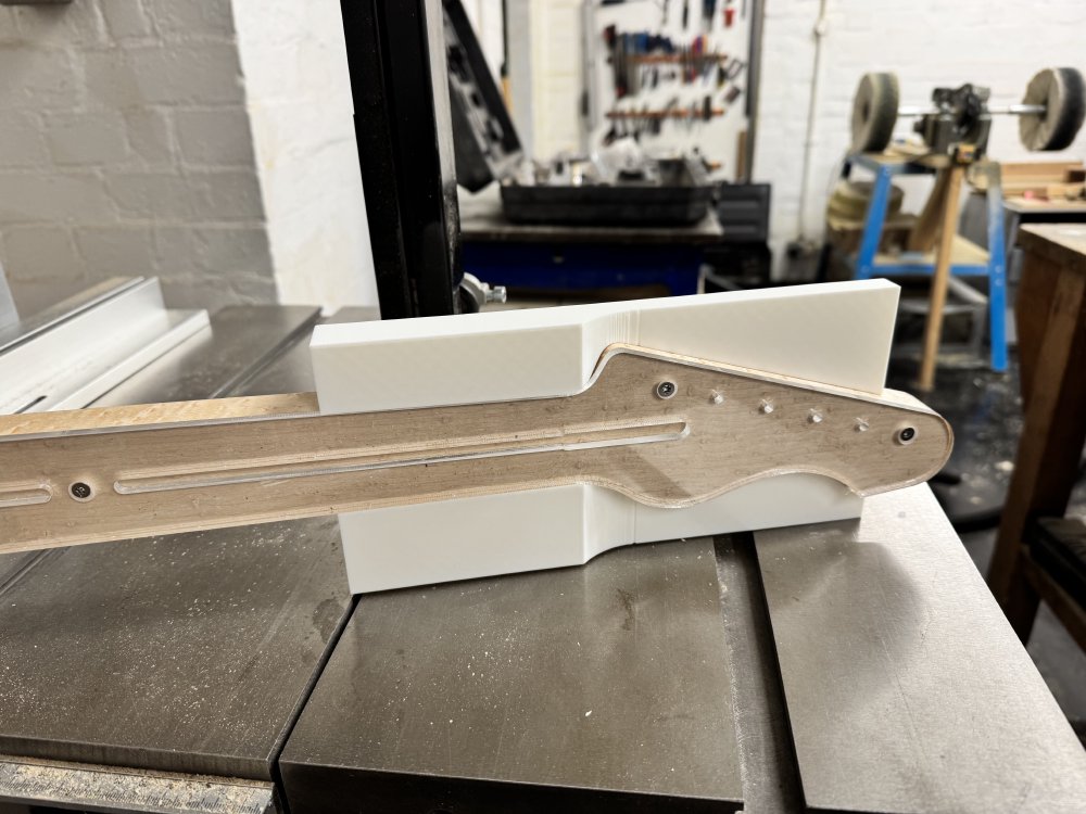
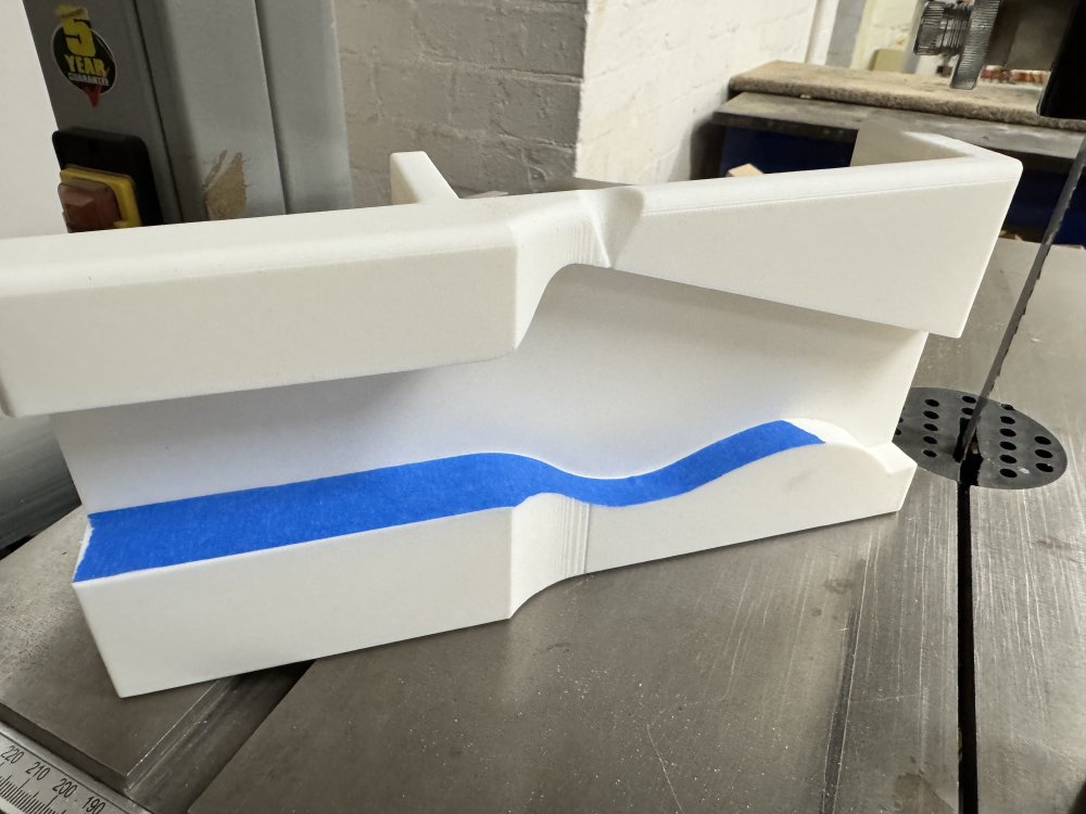
Another print session later, and I have version two in the workshop ready to test:
The first observation with the new print is that although I didn’t change the recess for the neck, it’s slightly different in size to the last one: 3D-prints are known to have small changes in sizes depending on things like temperature and filament variance, so it’s not the biggest surprise. It’s a small enough change that just some masking tape is enough to remove the slight wobble it caused:
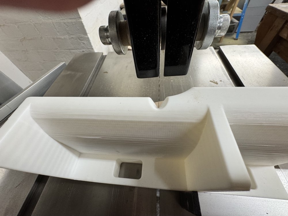
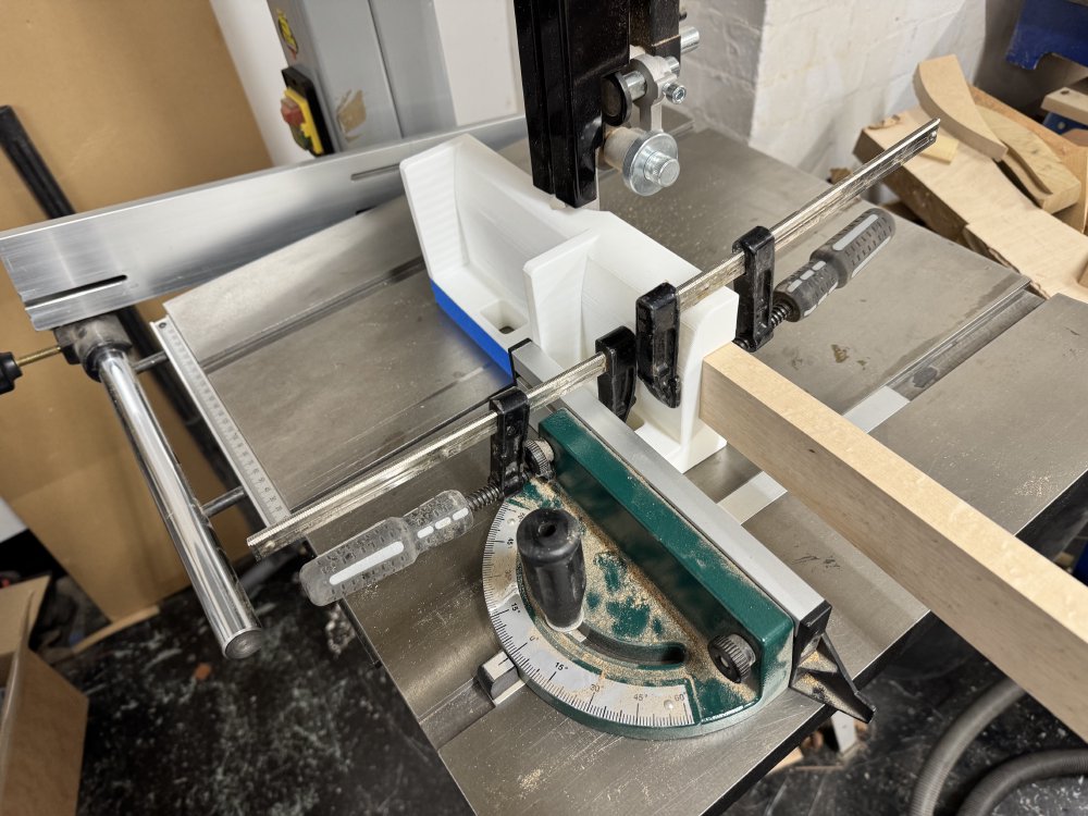
With that fixed, I can now confirm that the new print sits better on the fences on the bandsaw and I can see the contact point with the bandsaw blade for the first cut (and you can see how without that gap the contact point would be obscured):
And in the end those speculative clamp holes did come in handy, given how short the fence for perpendicular cuts is on my band-saw. They’re not ideally positioned truth be told, but good enough to use:
And so with all that, I could finally make the first cut:
All this for a single cut thats less than 5 mm deep! :)
With the first cut done, I could now make the longer cut that removes the rest of the material for the face:
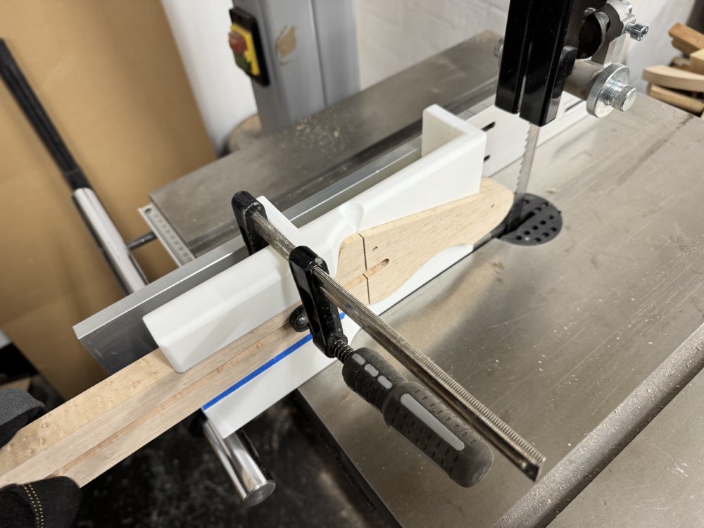
You can see here that the blades that I added to the back are the main guides here for this cut, and they worked a charm to keep things straight, and so a minute or two later I added another headstock blank to my collection:
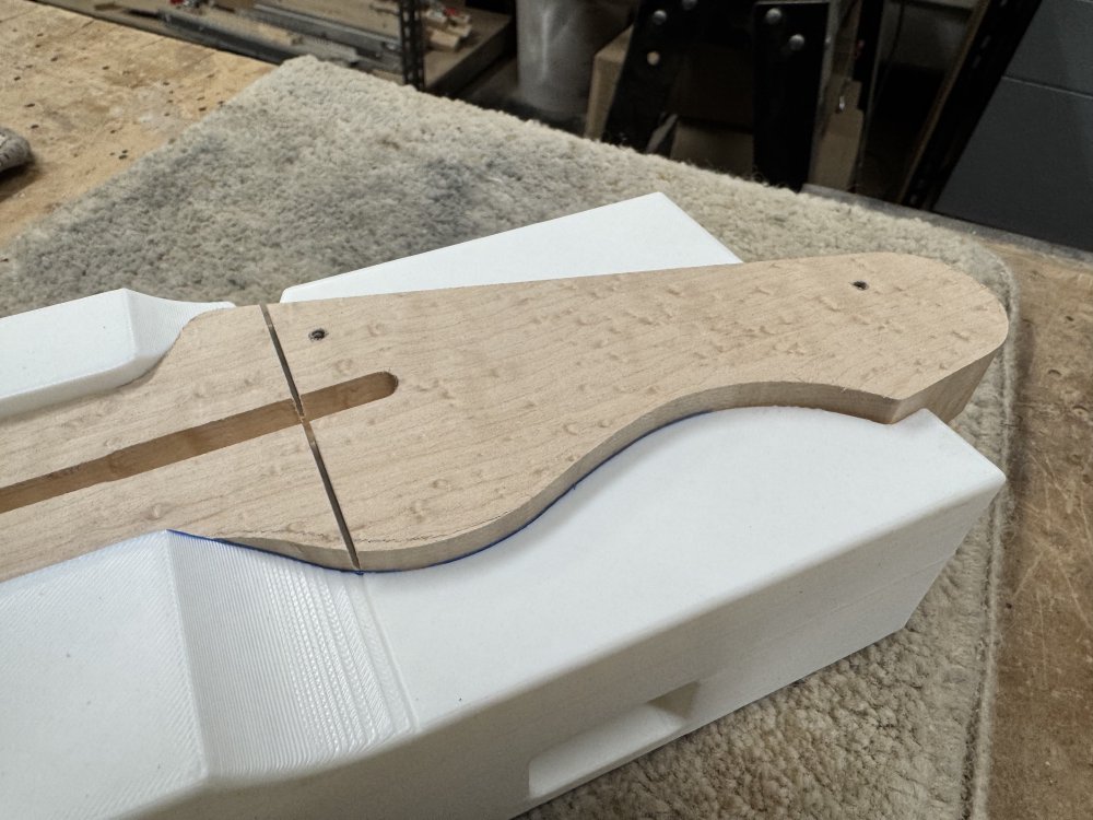
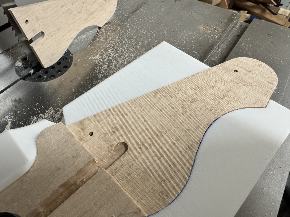
And we have a level headstock:
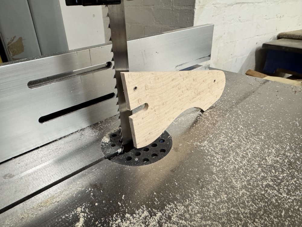
However, there was a problem with the cut, and the root cause sits somewhere between design fault (i.e., past me was to blame) and user error (i.e., current me is to blame). You can see in the above photo, and more clearly in the following photo, that the cut was not particularly clean. I mentioned in the last post that the band-saw wasn’t cutting cleanly and I wasn’t sure why, but I had since refitted the blade and tweaked the tension properly and it was cutting nicely before I did this, so I don’t believe it’s the band-saw’s fault. I think the root cause can be seen in the following photo, where you can see the marks in the wood extend into the plastic of the 3D-print:
Basically the blade was too close to the 3D-print, and as the blade comes down to make the cut it’s grazing the surface of the print which is causing the blade to deflect out a bit and wobble. We can put this down to user error in the first instance: I didn’t align the blade and the jig correctly. Because of the limitations on the size of the jig, it doesn’t go all the way to the end of the neck, so I’d drawn on with pencil the cut line all the way to the tip of the neck, but the blade is thicker than the pencil line, and I failed to allow for that.
The design fault is why did I have to do that at all? There’s a UX error here: because I’d clamped the neck to the jig to hold it in place, freeing up my hands, it never occurred to me to remove the neck from the jig to test my alignment. The moment the neck was clamped into the jig that was it, they were one in my mind. Had I not had that in my head, then I could have ran the jig along through to check clearance. The other design fault is I limited myself to just a single printed part: although the size of the printer’s bed constrained the size of the jig, I could have made an extension as a second print to cover the end of the headstock and give me a guide.
All good learning for next time. Thankfully the damage to the neck isn’t that bad, and it’ll sand out, which will be a form of penance for me.
Rest time for the jig
The new jig having proven its worth (but perhaps disproven my worth), it now gets to wait for its final act in the building of this neck, as the next step was to glue on the fretboard:
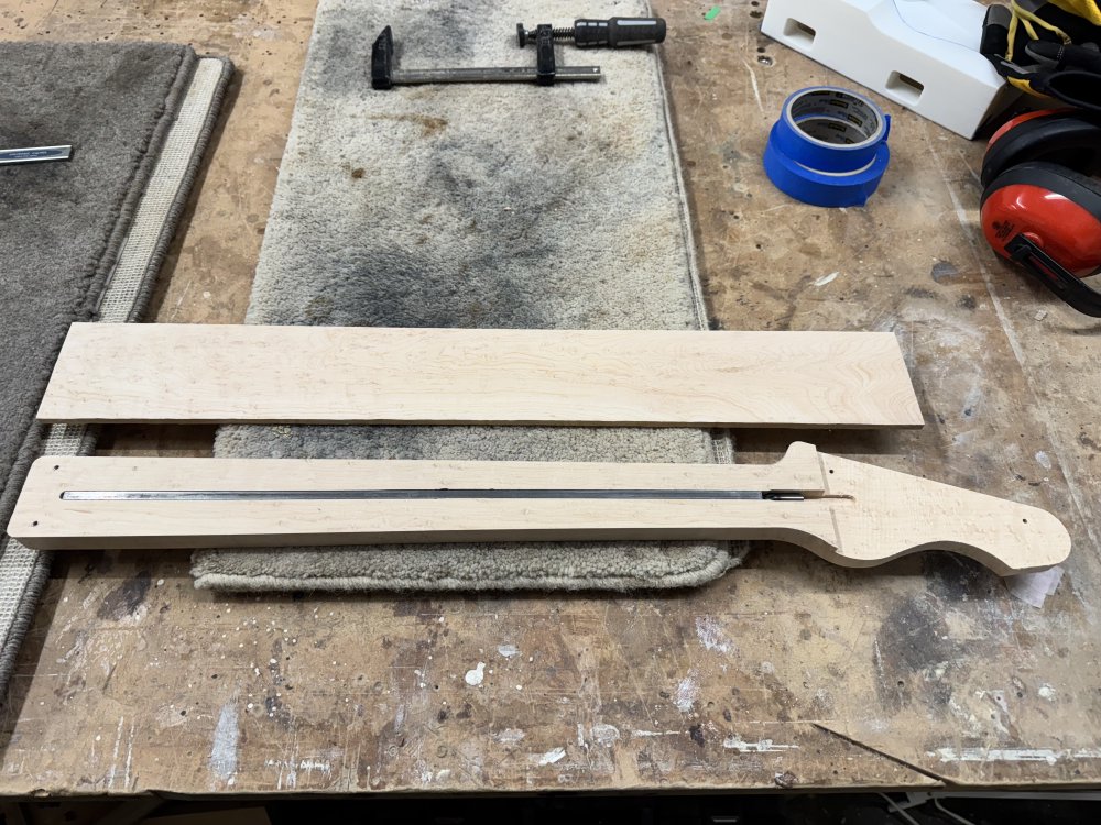
It got glue added, and then clamped up, ready for my next trip to the workshop, at which point we can see if the jig will fare as well on the spindle-sander as it did on the band-saw: