Investigating 3D printed parts for the new guitar design
Published 14 Jun 2021
In today’s catch-up notes, we’re going to have fun with 3D printing, and end up with a tidier desk. What more can you ask for?
If you want the context for this, then please have a look at last week’s post to see why I’m doing this, but otherwise hopefully this is a useful documentation of the process I used to work out how to print some weird organic/geometric shapes like the ones in this guitar design:
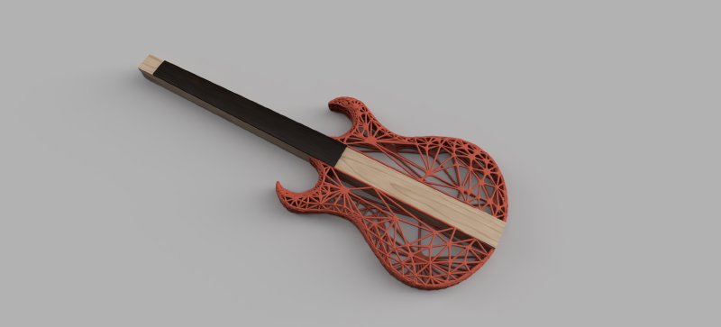
The question I want to answer today is can I make a 3D printed body in that style: Can I design it? Can I get it printed? Will it be strong enough? Until I know the answers to this I don’t want to put too much effort into refining the above sketch, as there’s no point spending hours designing a guitar that we can’t build. So, let’s see if we can get some answers.
As with acquiring any new skill, I started off by searching through various Internet based tutorials on how I might make the organic strut based design I had in mind. There’s not as many out there as I expected, but of the guides I did find, the best was this one by Autodesk’s Brad Tallis, which was simultaneously both amazing and frustrating (though the frustrating bit isn’t Brad’s fault I hasten to add):
What made it amazing is that what Brad is making is clearly similar to the kind of structures I had in mind, and he does an excellent job of walking you through how to make Fusion 360 generate this kind of design; I’m going to summarise the approach below a bit, but if this whets your appetite to make things like this yourself then I recommend giving Brad’s video a full watch.
However, it does end up being frustrating as the models you produce with this technique in Fusion 360 are very difficult to work with, particularly in terms of getting the organic shapes to interact with the duller but essential unorganic shapes you’ll need to add in any real world application: you’ll need to add some mount points for example to have it interact with other parts, or you’ll want to make a flat base part, or such. Whilst Brad’s example doesn’t do this, most applications where I’d want to use this technique would require it to interact with other things, and that process feels very fragile and unpredictable. Let’s walk through a practical example and hopefully you’ll see what I mean.
As an example, I took Brad’s vase holder example and shortened it to let me make a pen-holder for my desk: I’ve lived with RSI for years, and thus I have an Apple Pencil and Wacom Tablet pen in constant use whilst also cluttering my desk, in addition to regular pen and pencils, and this seemed like a good excuse to solve that whilst learning a new technique.
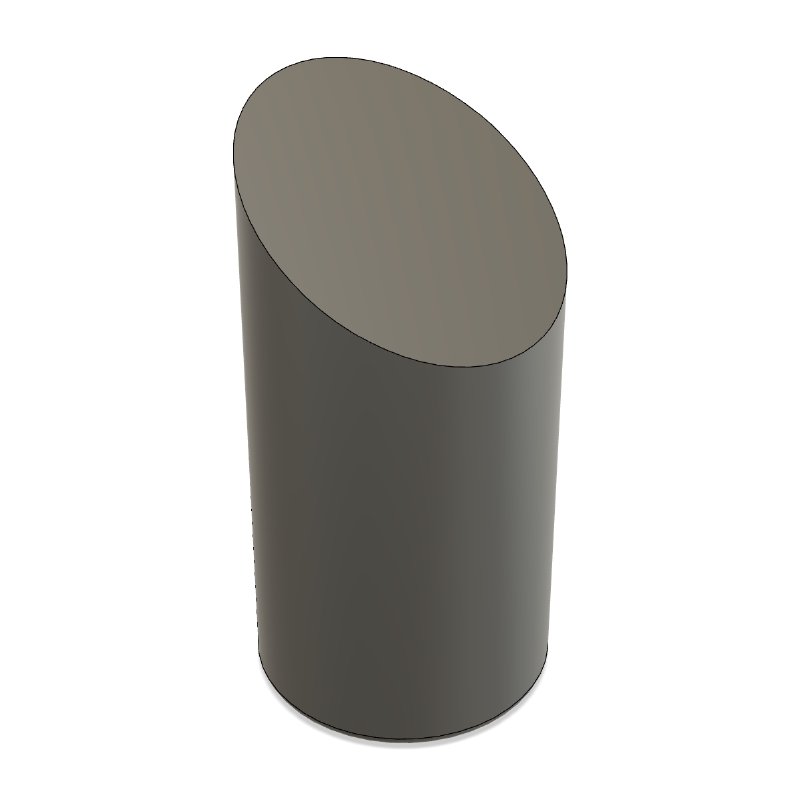
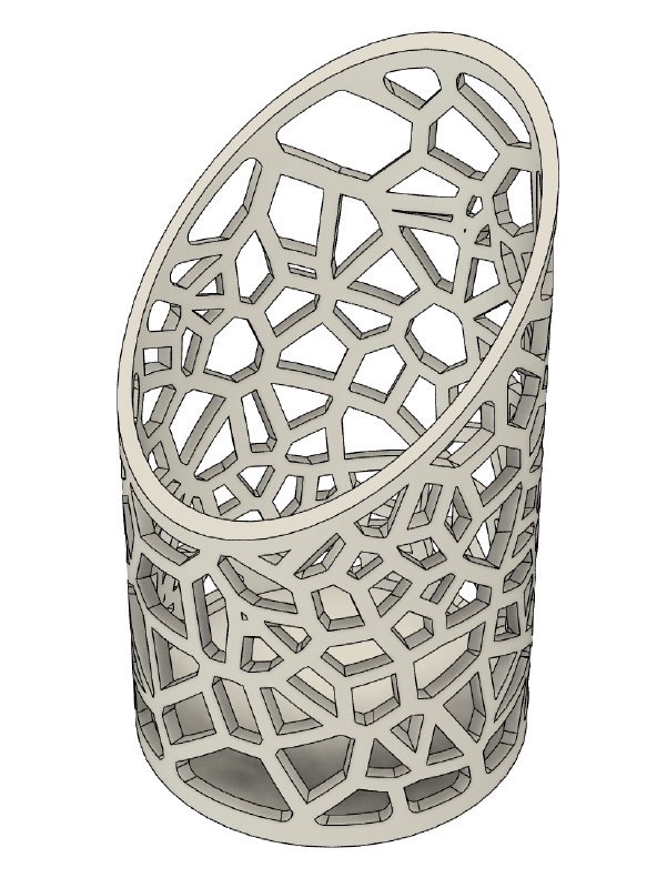
The basic approach of Brad’s method is you make a shape that matches the outline of the volume you want your mesh structure to cover. In this case a shortish cylinder with a rake to the top:
As a quick aside, the way I would do even this basic model was totally different from how Brad made his, which made me miss the old Fusion 360 Show & Tell sessions I used to run at Makespace, where you’d get to see the process of how people made things in Fusion, not just the end result. I used to learn so much from just watching other people do what they thought of as the mundane part of their project. Ah, halcyon days.
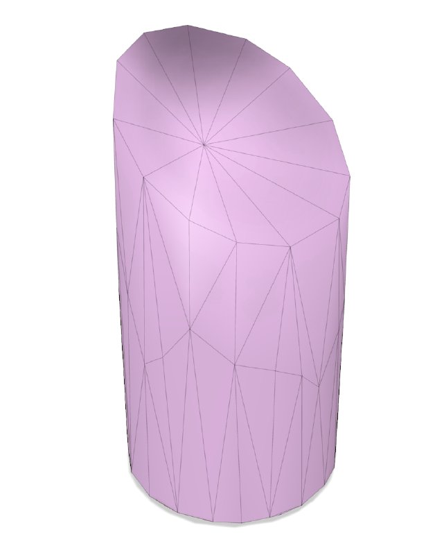
Anyway, back to the task in hand. Having defined the basic geometry, you then convert it from the standard “b-rep” model form in Fusion to a mesh model, reducing the standard polygon density as you do so, and then you re-mesh it again and play with those tool options until you get a more funky arrangement of polygons that appeals to you:
What you have now looks like a model, but we’re not interested in the model itself, just the vector edges that we’ll use to make another model based upon. So the next step is to select the edges that you want:
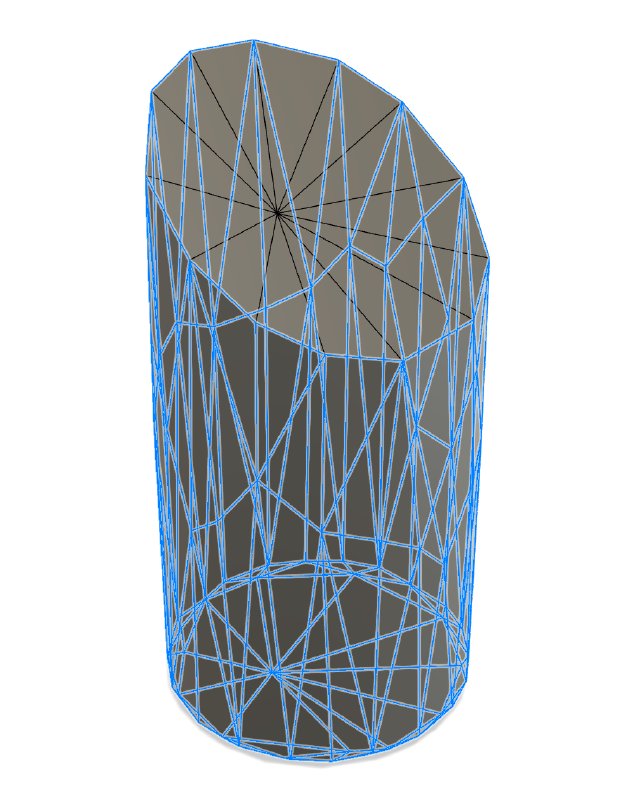
It’s not that obvious, but here I’ve not selected the edges that would close the aperture in which the pens will go into my pen-holder, and as per Brad’s tutorial I’ve opted to deselect some of the ones on the body for aesthetic reasons to make parts of the design more open.
Once you’ve done this you then use the pipe tool from the forms tab in Fusion to make the frame:
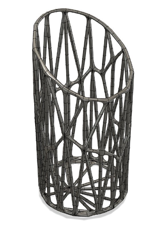
And blam, we have a nice organic low-poly style structure! But it’s not over yet - we’re about to hit the first bit of friction with this approach in Fusion 360, and the root cause of why these models are a pain to work with.
Whilst what we have here looks great, but is in fact a flawed model: Fusion 360 can’t really cope with the faces of these struts joining together at such acute angles and gets upset about the struts clipping into each other. Thus you can’t turn this back into a b-rep model that would then let you 3D-print this. Brad solves this using a technique in Fusion 360 called “Boundary Fill”, something I’ve not used before; it seems similar to combine bodies, but you can use non-regular objects as tools in the operation. In effect what Brad does is create a new standard model that is bigger than the volume of the model he wants, and then asks Fusion to remove all the parts that aren’t in the mesh model. This leaves you with a b-rep model that looks the same, but now we have it as a solid volume in Fusion’s modelling world rather than as a mesh of surface tiles. At this point you can now use the 3D print export tool in Fusion and Brad has his nice vase holder. Roll credits on Brad’s tutorial.
I was very happy with this, but before 3D printing my pen-holder I thought I’d quickly add a solid base to it, so that the pens and pencils don’t end up drawing on my desk when I put them in. Unfortunately, it was at this point I discovered that although you’ve tricked Fusion into generating a b-rep model of your mesh, it still really isn’t a thing it wants to work with.
In particular, if you try and merge it with another b-rep part, such as a flattened cylinder that would act as a base to your pen-holder:
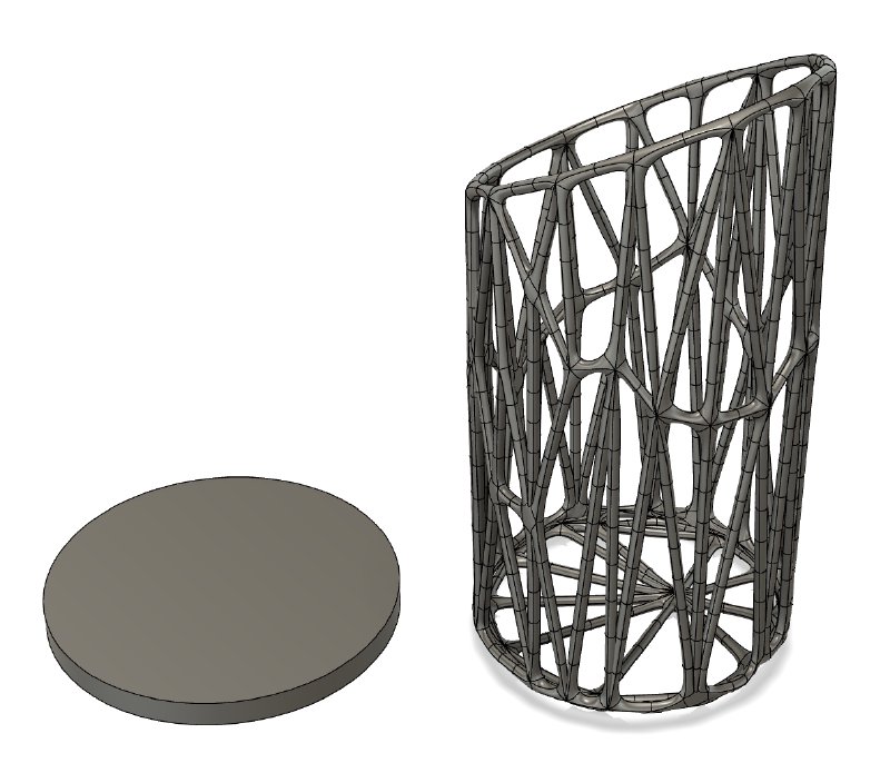
Normally I’d just overlap these two objects and then get Fusion to combine them into a single volume, but in doing this I get an error from Fusion saying that the model isn’t valid, and try as I might I just couldn’t seem to get them to want to combine.
This is somewhat of a show stopper then for making anything with this technique that then might interact with other forms, such as I’d want to do with my guitar design. To have this as a part in something bigger you’ll most likely want to add regular parts that you can then use as attachment points to other objects, and its clear Fusion doesn’t really like to do that with this sort of model we’ve created.
I spent several sessions with Fusion trying to solve this through different approaches: editing the original mesh to add the disk there, trying different conversion techniques, and even just trying something not based on this technique at all (more on this later). In the end I managed to fudge it enough to make me thing I have a way forward, but I’ll admit it is a kludge and as an engineer makes me nervous committing to build something based on this - but for now it’s the best I have and it did give me something I can work with and sort of repeat.
What in the end worked was ensuring that none of the faces of my base disk interacted with the areas where the struts in our organic shape meet. As we noted above, Fusion doesn’t like that these struts clip into each other, and it still is the case even once you’ve covered it to a b-rep form, and so it doesn’t want to play if you try and have your disk clip through those areas. So in my case, if I made the flattened cylinder for my base slightly wider than the pen-holder and so that the top and bottom we clear of the mesh part that formed the bottom section of my pen-holder, then it worked fine, but if you accidently clip one of these areas where struts join Fusion just throws up its hands in horror.
But you’re not home free yet. At this point I thought that the base of my pen-holder post-combine was now a sensible shape, so I’d be able to edit it normally, but no, the same problem exists. Even though I have combined the mesh and base successfully, internally Fusion still knows about the mesh that has been subsumed and you can’t create features that clip into that space, even though in my view as a designer it has gone away, being replaced by the disk part. In the end I started again, remaking the mesh model, but this time not having any struts where the base would be to let me work more easily in modifying the base because there was nothing to clip with.
So, does this technique work? Kind of. I’ve proved it works well enough that I can make a 3D print of my pen holder, but I’m still worried about making a body like this and not being able to model mount points where it must join to the wooden part or where I want to mount things like the volume and tone controls.
So, having made a model, I next went to try to 3D print it on the ultimakers at Makespace. Unfortunately the design I’ve made really isn’t well suited to filament printing it turns out. This is what it looked like coming off the printer:
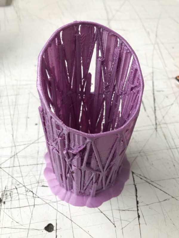
With this kind of 3D printer it needs to put support material in to stop the part collapsing due to gravity as it prints. Normally the support material is easy enough to remove, but the mesh struts are so thin that they just snapped as I tried to remove it. Indeed, you can see in the above some of the struts hadn’t even survived printing.
Still, it did show me that the model itself was interesting enough to warrant further printing attempts, but for that I’d want to print with a different printer, such as a resin printer like the FormOne I’ve talked about here in the past. Unfortunately Makespace no longer has such a thing, having sold off the FormOne printer it had due to lack of use vs high maintenance overheads (totally the right thing for Makespace to do, just unfortunate for me).
Thus instead it was time to jump to something more professional, and I turned to Shapeways, which is the print on demand service that I’d most likely be using for the final guitars if this project gets to completion.
Shapeways offer a wide range of materials you can print in, and a variety of finishes in each of those, and so I picked the one I felt most likely to be the one I’d want to use for full production of the guitar parts to get a feel for whether it feels suitable in person. I opted for their versatile plastic option, on the grounds that it is made from Nylon so should be strong enough, and comes in a wide range of colours that I could then offer on to clients asking for guitars.
Ordering this way is easy enough, you just upload your STL file, same as I’d use for the Ultimaker print, click a few options and provide them with payment. It is not a cheap process - I paid £1.50 at Makespace to print the first test version, whereas with Shapeways it cost me €65 - quite a price difference! If you scale that up you can imagine a guitar body is going to get reasonably pricey. However, not excessively so - the wood for a guitar body already costs in the region of £70 for good but not AAA wood and that’s before I’ve done any work to it, so if the body print comes to a few hunderd pounds, it’s still an acceptable cost comparatively.
A week after I clicked print, I got my print delivered in the post:
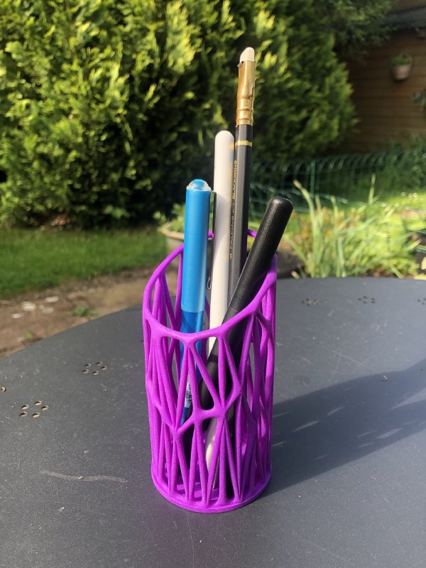
I’m really pleased with the results, and not just because I have somewhere to keep my various writing implements now. The print is clearly leagues better in terms of finish compared to the Ultimaker print: there’s no layering, and it’s had the mid tier of finish applied, so it feels very nice in the hand. The colouring is solid throughout, and is a really rich colour. And finally, and most importantly, it’s really quite rigid, even given the narrow struts in the design, whilst still being light weight - 30g almost on the nose. Note that I also did not finishing to the above part: it came ready to use straight away.
So I count this as a successful de-risking exercise, and means I can now press of with the next stage of the guitar build, which will be taking the sketch that I have in CAD and refining it to a point where I know how I’m going to attach the 3D printed wings and I’ve convinced myself I can make the pretty mesh part integrate with the wooden parts.
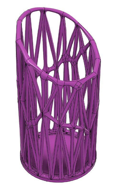
One last thing I want to mention that worked, but wasn’t to my tastes but might be of interest to others: I did try using a Voronoi pattern generator as an alternative way to get the mesh like effect:
To generate the above I used a paid-for plugin for Fusion 360: 3D Voronio Studio. The have some nice tutorial videos that explain how to get started, and after all my fighting with the meshes I made myself this tool was a breeze to use, and if this is your thing then I can readily recommend it.
Personally thought, I preferred the slightly more organic look of the meshes made via Brad’s tutorial (though I do think their examples with thinner lines look better than my pen-holder in this style above). Still, if this kind of pattern is something you like this is certainly a great tool to use.