A week out the shop
Published 7 Dec 2020
Unfortunately another week where I didn’t get into the workshop, for the same reasons as last week - a mix of client work and being a bit under the weather. But I did get to do one interesting thing that’s worth noting - I virtually attended a one day course on PCB production ran by Adrian McEwan.
The course was centred around using the popular KiCad set of Electonics Design Automation (EDA) tools for designing PCBs. KiCad lets you draw out a circuit you want to build, specify the parts you’re going to use to build it, and then do the placement and routing of the circuit ready for sending off to a PCB production house.
KiCad is an open source tool chain, and in general I think there’s an assumption that open source means slightly less good quality than paid for (e.g., whilst FreeCAD has a lot of enthusiastic users, I think for most people Autodesk’s Fusion 360 is a more capable tool), but KiCad really is a well polished tool chain when compared with say Autodesk’s Eagle (at least based on my experience from when I last tried to use it a year or so ago). I guess this might be in part because quite a few big entities had funded development of KiCad, meaning it has had a lot of effort go into it by people who actually want to use the output of that effort. But certainly whatever the reason is, having used Eagle a little bit and now spent a day in KiCad, I can certainly say I prefer KiCad.
On the course we had a simple LED badge example Adrian walked us through, but then in the second session I took a circuit I was more familiar with, that of the classic Fuzz Face pedal that I built a batch of in early 2019.
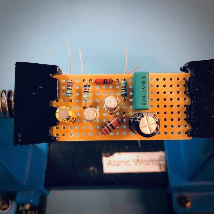
Here’s that same circuit input into KiCad (only with the other input bits that are missing on the above board):
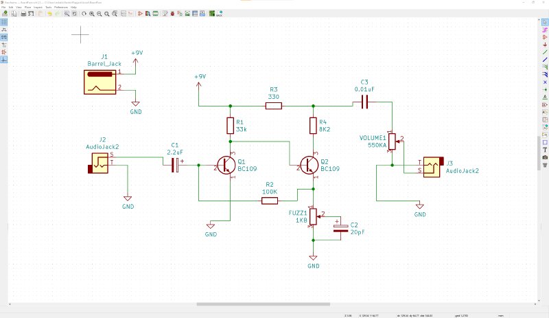
Once I’d entered that, I told KiCad what physical components I’d use for each bit of the circuit (I wanted this kind of resistor, this kind of transistor, and so forth). For this I just based it on the parts I ordered when I made the original set of pedals on veroboard using old style through hole components. If I was actually doing this today then I’d probably use surface mount parts where possible based on the advice from Adrian. Once I’ve given all this component information to KiCad, it then knows the physical footprint of everything, so we can move onto the PCB design:
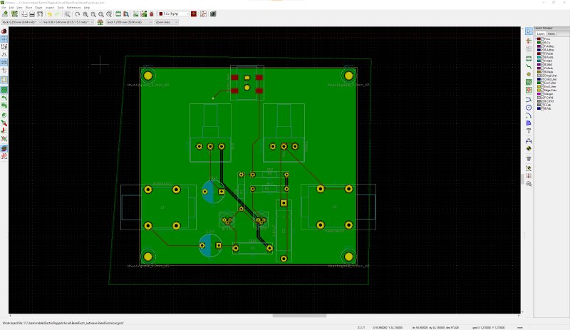
Not exactly a work of elegance, but this was my first layout :) I could even get a 3D render of the circuit board at any point:
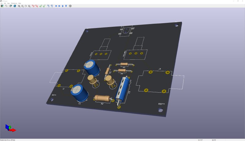
You can see that for some components there KiCad didn’t have a 3D model, so it’s not a perfect rendition, but if I was relying on this 3D view more Adrian’s course did cover how to load your own component designs into KiCad for those instances where the standard libraries of parts that come with KiCad aren’t sufficient.
Of grater importance to me was KiCad’s ability to export the 3D model as a step file which I could load into Fusion 360:
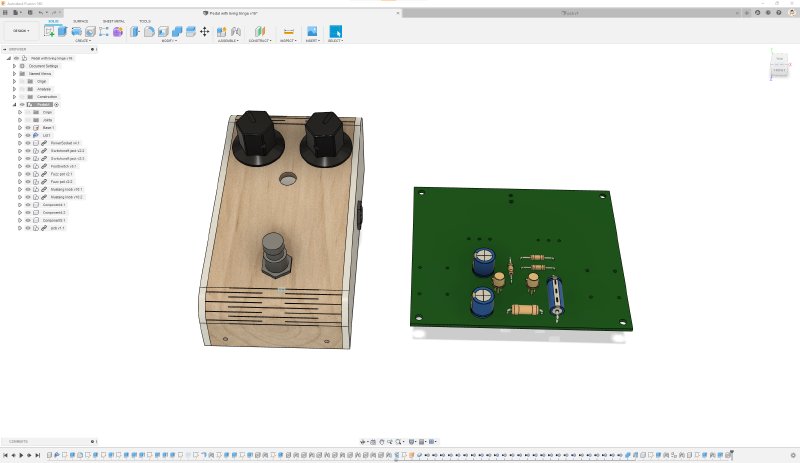
Here you can see that I totally failed to design a PCB that would go into the case I made for the pedals, so it was back to the layout stage for me again at this point :) This workflow isn’t as smooth as you get if you use both Fusion 360 and Eagle, where you have your changes in one tool reflect almost immediately in the other, but for the kind of things I make it’s good enough for now and certainly something I’m happy to trade for KiCad’s nicer user interface.
At some point I do need to follow through to make an actual PCB. It’s very easy to do small PCB production runs these days with places like OSHPark and JLCPCB.
My thanks to Adrian for putting on the course - he’s mentioned on his latest blog post he’s thinking about running it again in the new year, and I can highly recommend it if you’ve always wanted to have a go at moving up from breadboarding to getting your own PCBs made.