A week in the shop
Published 18 Oct 2020
Last week I mentioned I’d ordered some bits for the workshop and I’d talk about them when they arrived; the first of those turned up and I put it immediately to use: a router bit with adjustable bearing to let me make the edges on the control cavities for the lids to sit on.
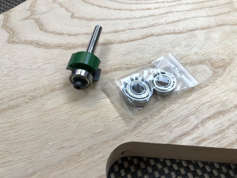
This is a router bit for a hand-router that is designed for routing steps into the side of things (if you’re interested in the specifics, the product page for this specific bit is here). The bit itself has a diameter of 24 mm, and the bearings are sized to give you an overhang of 1 mm, 2.5 mms, or 4 mms. The 1mm can be used for routing binding channels around the edge of the guitar, something I’d like to try down the line, but in this instance I wanted the 4 mm step so that I can make the lip for the lids to go on the control cavities, as shown here:
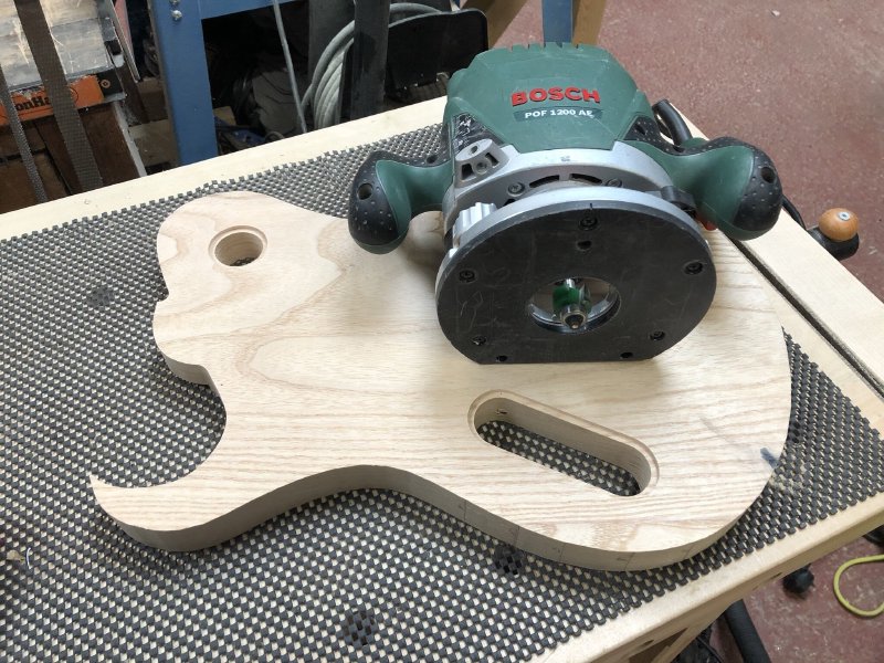
It worked well on the workshop prototype build, so I also did the cavities on the Corvette build:
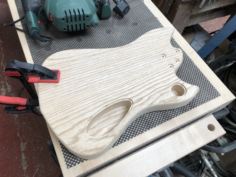
It works a treat. The maximum step of 4 mm is slightly narrower than I’d planned for these, so I’ll need to see how well that works in practice. Unfortunately, at least with Trend router bits, the next step up is quite a lot larger (basically a rebate cutter) so 4 mm was the closet match to my design.
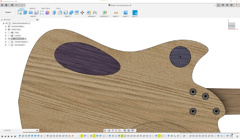
Having cut the lips, I went back to Fusion 360 and updated my model to match what I had cut and add the screw holes to the lids, paying close attention to how close I can make them to the edge of the cover to ensure they grip in the 4 mm lip I have:
My task next week will be to laser cut the covers themselves. The intent is to do them in wood, but as a first pass I’ll probably use whatever scrap acrylic I can find in Makespace to let me test the sizes for fit.
On the Corvette build (which the observant of you might note is called “Robin” in Fusion 360 still - I’m terrible at naming things) I drilled all the holes for the bridge mounting and to pass the strings through the body to be anchored on the rear in ferrules- a quality hour or so with a pillar drill. I failed to take many pictures of this, as it’s been a while since I’ve ran through this process, thankfully I wrote it up in detail last time I did it in anger (sigh, almost a year ago!), so you can read that for more details on the process if you’re interested.
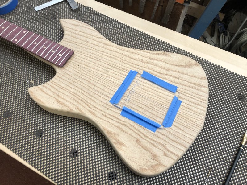
In the above picture I’m at the stage where I’ve used a ruler to measure out where the scale length is on the body, I’ve put the bridge on the body to check where it should be relative to that, and I’ve noted where the screw holes for the bridge need to be. I then mount this template to let me drill the initial pilot holes for both the bridge mount screws and for the holes where the strings run through the body (again, see the older post for more details).
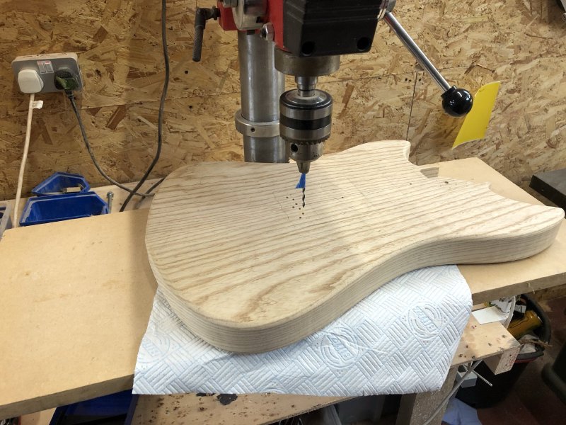
In the above picture I’m about half way through the process. It takes two different templates (including using one of them twice, once per side) and 28 individual drill actions to entirely drill all the holes required for the bridge, the string ferrules and for the holes that route the strings from the front of the guitar to the back. It’s slow, careful work, but I actually really enjoy this part of it: there’s a great sense of satisfaction getting everything to line up neatly on both sides of the guitar by hand like this.
I mentioned a couple of weeks ago that on the strat clone that I’m fixing up I needed to check the pickups worked before cutting it a new pick-guard on account these pickups being an unusual size. So I broke out the soldering iron and wired everything up, replacing the old dodgy components with fresh new ones:
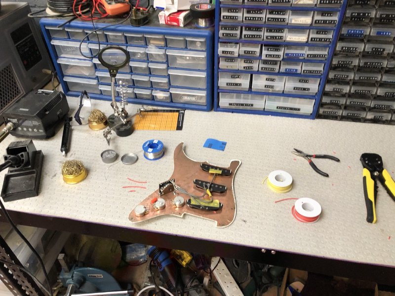
Although I knew it needed new pots, I had hoped to re-use the rest of the components, but unfortunately the old pickup selector switch had to go, as the tip on the switch was glued on, so there was no way to insert it into the new pick-guard. Amusingly, not only are the pickups on this guitar slightly undersized, but so was the pickup selector switch, which was smaller than regular ones. To mount a new one I had to cut the slot longer and drill a new mount hole into the old pick-guard (safe in the knowledge this one will be replaced).
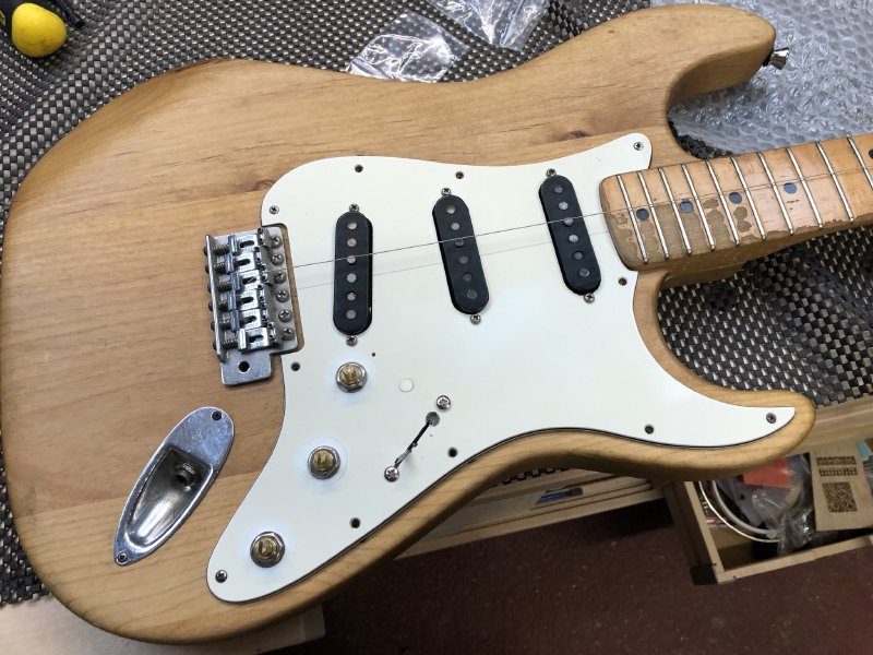
Thankfully after all this the pickups work fine. So now I can set about making a new pick-guard.
Finally, a few weeks ago I mentioned I ran the body for the workshop prototype guitar I’m making through a thicknesser to level it, but that because the wood it’s made from is so soft, the machine had left an imprint on the edge where the guide rail rubbed against the side:
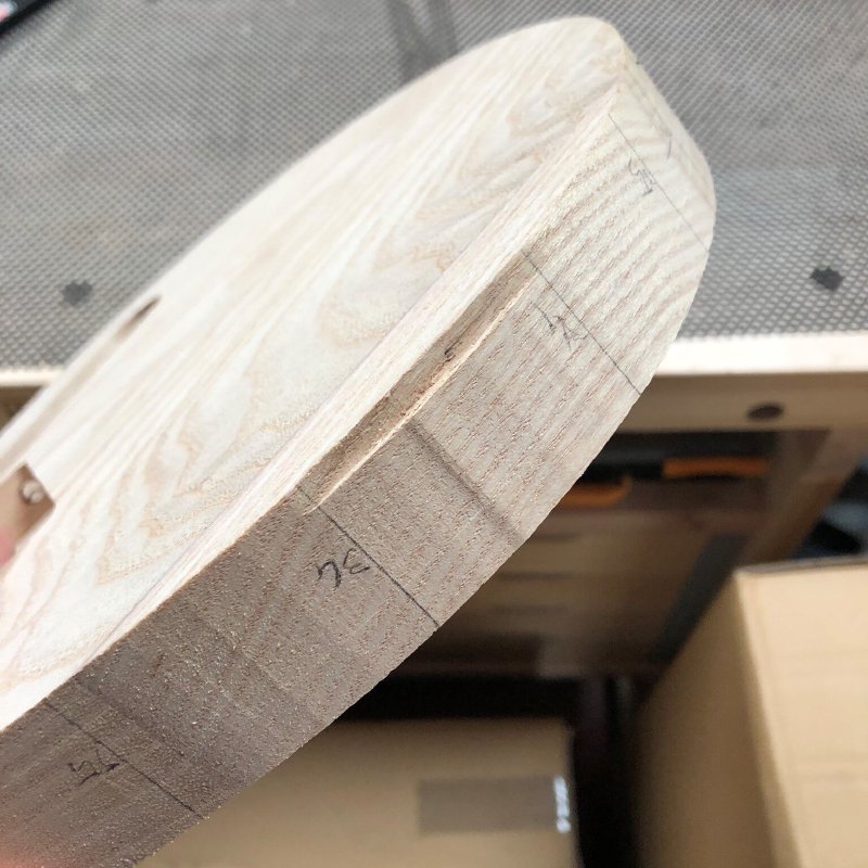
Whilst I could just sand this out (and do the same on the other side to even it up), first I wanted to see if I could restore some of the shape by using steam expansion.
In general if you have compression damage to wood then dampening the wood and using something like an iron to cause the water to turn to steam can make the wood fibres expand back. I used this successfully in the past to save a neck that some unknown person damaged whilst hung up in Makespace, so I thought I’d give it a go here:
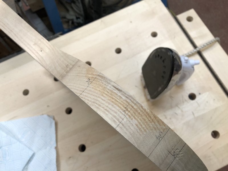
It’s hard to tell from the picture, but this did work for the most part. The results were not as successful as before, because there was some tearing of the wood fibres where there was a the step in the first picture, but it’s a lot better than before I started. This is good, as it means that whilst I’ll still have some work to do, the overall shape should not need to be adjusted that much.