A week in the shop
Published 23 Apr 2019
At the end of last week I had cut out the body template for the Corvette guitar, but I was still concerned about laser cut templates for routing due to the kerf you have from that process. The kerf is the material that is vaporised by the laser, which can be tenths of a milimeter, and so if you make a neck pocket template where you’ve lost some material and a neck template where you’ve also lost some material that will double up the error, and you may end up with a neck that is loose in the pocket. There was really only one way to find out, which was to make the rest of the templates for the Corvette design and see how good a fit I got.
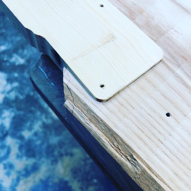
Having cut the templates I then got some scrap wood and cut out the heel of the neck:
And then the neck pocket:
Having made both bits, I was delighted to discover that they had a nice friction fit:
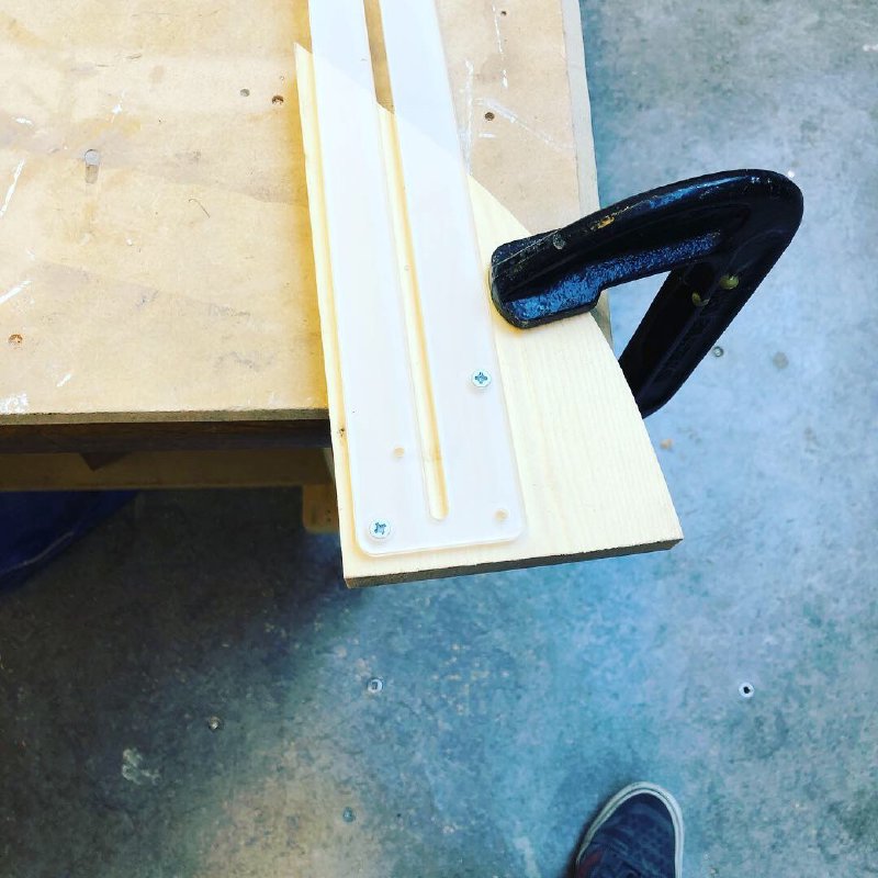
So in this instance the kerf wasn’t enough to cause any trouble, phew! But it’s definite an experiment worth doing if you’re going to be making things this way. I also tested out cutting the truss rod slot using my new 1/4” follow bit for the router.
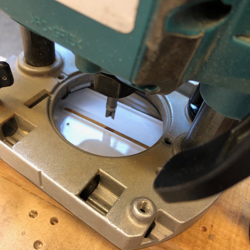
I was a bit nervous using a bit in a slot like this, and with such a small bearing (having had small bearing like this from cheaper bits fail), but it all worked well.
I realised that I had one other design issue unresolved with the neck for the Corvette design. One of the things I try and drill into people when I teach CAD is that just because you can design it doesn’t mean you can build it, and the software doesn’t know what you can and can’t do, so you have to make sure to review your designs to ensure you can execute them. This is an example of that, which I almost missed.
The idea on this guitar is to avoid CNC Routing where possible, so I’ll be doing the neck to headstock transition using the spindle sander and a jig to ensure the neck is perpendicular to the spindle. I did this for guitars #3 and #4, so this is nothing new, however with the Mustang style guitars I switched to a headstock with the truss rod adjustment end exposed, as I don’t believe in hiding the functional parts of the instrument. However, if we take a side profile of the headstock, the problem becomes evident: I can’t spindle sander the headstock down with the truss rod in place, as I’ll end up hitting the truss rod.
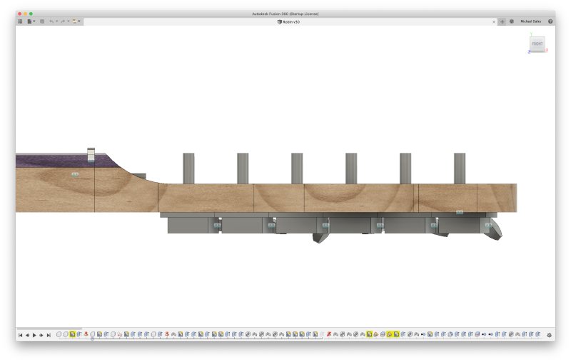
The truss rod is the little grey bit that sticks up on the curved section, which would prevent me betting the spindle sander to actually cut that curve.
I had a play with moving the truss rod such that the adjustment end was more recessed, either by using a shorter truss rod and/or moving the transition further, and nothing made me happy design wise. So I think I’m going to try sand in the transition on the main part of the neck before I glue on the fretboard, and then use a chisel/sanding to get the transition on the fretboard side lined up.
I did some practice with chisels, thanks again to Graeme who brought in some nicely shaprpened chisels.
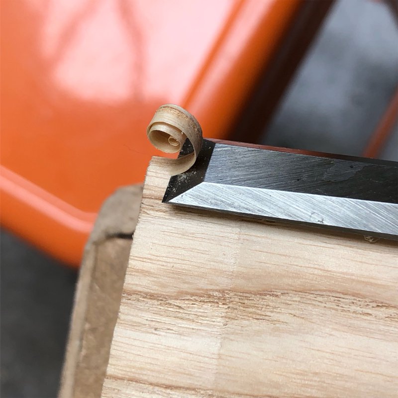
This game me confidence that I could use a chisel to help shape the fretboard. Thankfully I have a reasonable set of chisels myself, they just need sharpening on the tormec.
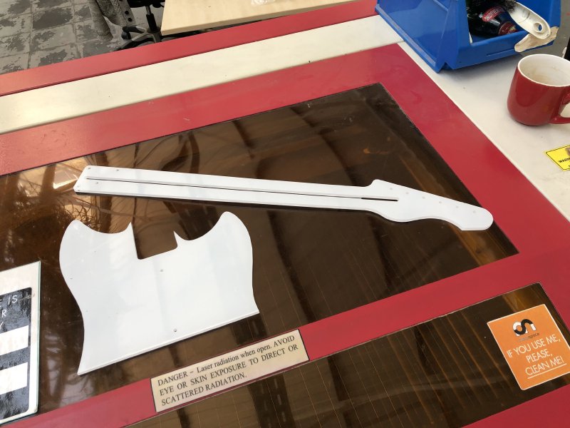
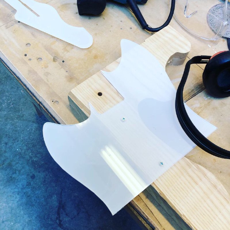
Whilst the Corvette guitar will be mostly CNC Router free, I still have to finish off the Recovery Offset guitar which relies on that (I could avoid it if I have access to a table router, but I don’t). The CNC Router is still playing up, and I can’t use Fusion 360 to generate tool paths for this current controller, so I sat down with Vectric’s vCarve software to try out making a pick guard this way.
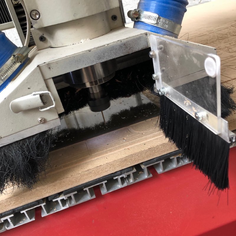
This mostly worked, but the acrylic I was using turned out to be quite uneven, so I couldn’t test adding the chamfer. Still, it validated using vCarve Pro. The workflow then was to use Fusion 360 for the design, saving a DXF file from the sketch in Fusion 360 for the pick guard and then importing that to vCarve Pro. Whilst I think vCarve Pro is a terrible tool for design entry, I have to say that for tool path generation it did everything I needed (though I’d still rather have used Fusion 360 if I could, as it just makes it a little easier to tweak things.
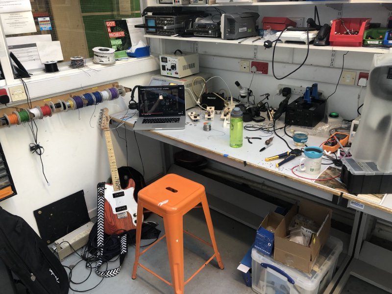
I currently have a backlog of half done projects, so I decided to burn a day of the easter break just ignoring the guitars and getting on with some soldering.
A while, to help me get soldering practice, I made a batch of fuzz face boards, and I finished making those playable. What I look forward to now is trying to see how different they are. There’s lots of mystique about vintage pedals etc. or how specific components have that magic tone, but given the tolerances on a lot of electrical components it’s quite frankly amazing if any two pedals sound the same at all. For example, most pots you buy are rated to within 20%, which is quite a wide margin. I also bought a batch of transistors and measured the gain value for them.
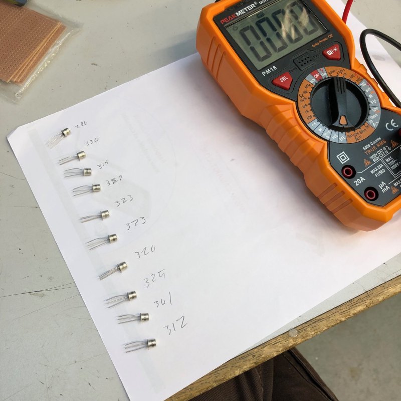
The gain varied from 284 to 341, which is again getting up towards 20%. So at some point I’ll get this collection of fuzz boards and see how they compare when put at the same settings. A lot of companies will buy components in bulk and filter them to ensure that the components are more tightly controller in how close to ideal they are, which is in part what you pay for when you get a more expensive pedal. But the idea that two pedals are totally identical, particularly for more budget brands, is quite clearly nonsense (though that doesn’t mean any are bad :).