A brief week in the shop
Published 25 Mar 2019
I finally got to spend a little time in the workshop this week, so I started with the Recovery Offset guitar build (I still a better name for this guitar). Now that the finishing is mostly complete, the first task was to go through all the hardware parts I have for it and set about fitting them, along with joining the neck to the body.
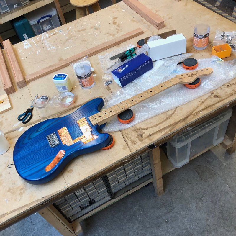
I was slightly stymied in this unfortunately by the spring in the pillar drill breaking, which means it wouldn’t return to resting position when released. Whilst the drill is still usable, there’s no rush to this build and I’d be gutted if anything went wrong (again) to this guitar, so I decided to park fitting the neck and the remaining hardware until a new spring arrives (many thanks to fellow Makespace workshop denizen Graeme for ordering a new spring!).
I did manage to select some pick guard material to go with guitar’s wonderful finish, thanks to Matt at Fidelity Guitars lending me some of his material to try out. In the end I selected a semi-clear tortoise shell type pattern that Matt had sprayed on the back with copper paint, giving it a wonderful shine, which I think both complements and contrasts with the peacock blues of the body. I’m very excited to see this combo in place.
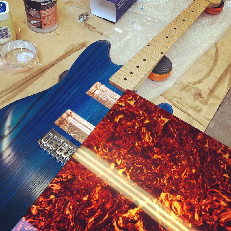
Having picked a bit of material, I sat down to work out how to make the pick guard on the CNC Router. I’d never cut acrylic on the CNC Router before: usually I’d cut acrylic on the laser cutter, but here I want a chamfered edge to the material, so the CNC Router was the way to go. I had a chat with Graeme about his tips for cutting acrylic this way as he’d done it before, which was mostly to have a slower cutter speed at around 8k rpm, then I grabbed some scrap material and went to do a trail run…
I used to own an older Ducati motorcycle from the late 80s, and my usual joke about it was that it was very reliable: it was always in the garage being fixed (ho ho). I fear my relationship with the CNC Router at Makespace is in a very similar way.
A quick recap for those who don’t read regularly: the CNC Router at Makespace has spent the last year playing up and breaking jobs, and so recently a group of us performed brain surgery on it and swapped the original control electronics for new control electronics, which were selected after much testing on a jig. Since then many members have used the upgraded CNC Router successfully, and I’ve used it in training successfully, but until this moment I’d not tried using it myself for any actual work. This is one of the dangers of a place like Makespace: whilst I enjoy helping others out in the space, if you have limited time you find that you end up spending that helping others do their projects rather than making progress on your own. So I was quite looking forward to using the new CNC Router to make a thing.
So I made a quick test design in Fusion 360 to let me test cutting a chamfer on acrylic, which looked like so:
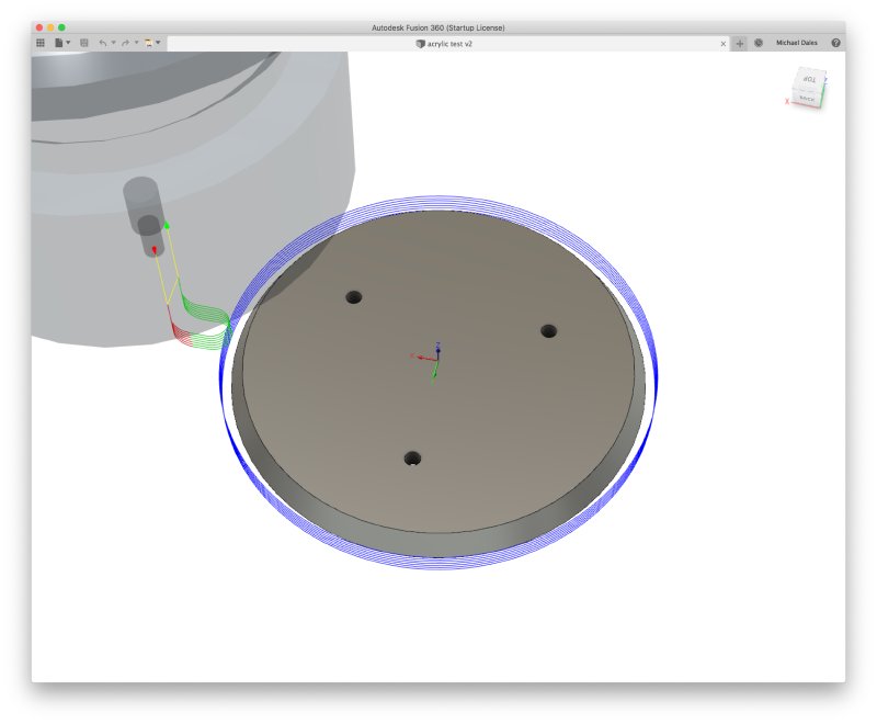
There’s three stages to making this: drill some holes to let the cut out circle be held in place after the second stage, the second stage is to just cut a circle with a straight edge to free the piece up, and then the third stage is to add the chamfer along the now liberated outer edge.
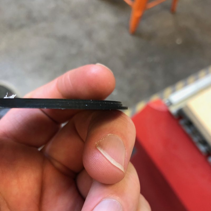
Whilst the first stage passed without incident, the second stage did not go well. As the machine cut the contouring tool path, which is the one highlighted in the above picture, it started misbehaving. In the diagram you can see a green and red bit of the toolpath where the the bit is leading in and out of the circular cut; when executed on the machine it would move very rapidly on the lead-out, causing the machine to skip and lose track of the origin, so when it cut the next layer it was out in both the x and z-axis. Thankfully it was only out by mm, so it wasn’t too unsafe, but you can see the result here of what should have been a flattened cylinder instead has stepped sides, and should have only been cut half way by this point:
After it failed I felt a second pair of eyes would help, so I pulled in poor Graeme to see if he could spot where I’d gone wrong, hoping it was user error rather than machine error, as I’m easier to correct. We tried running many toolpaths, both variations of what I’d just run and some other different designs, and we could reliably cause the machine to fail either in the lead in or lead out motion in designs generated from Fusion 360. At times it actually lost track by a few tens of mms, which is really quite unsafe. As such we had to put a temporary restriction on using the CNC Router with Fusion 360 generated toolpaths until we figure this out.
To be clear, it’s not Fusion 360 that is at fault here, but rather the set of g-code that our controller will work with isn’t as good as we thought it was, so using the generic GRBL exporter in Fusion 360 (which seems to be the most generic export option for machines that don’t have a specifically supported post-processor in Fusion 360) is generating g-code that our CNC Router controller can’t cope with. What’s worrying is that after examining the offending g-code, it seems the errant commands are just simple arc drawing commands as far as we can tell, with the possible addition that they have an arc in the Z axis unlike other ones that run fine which only move in the x and y axis. We played around for over an hour and didn’t get to the bottom of it, so this is still a mystery and once again I can’t use the CNC Router for my guitar work.
All in all, it’s a bit of a sad thing to be back to having an unusable CNC Router again despite all the effort we put into fixing it. We still have the Masso controller unit to try, which does officially support Fusion 360, so we can try that. However, it is more complex, and what we like about the pendant controllers is they tend to do fewer things and have dumber UIs which is actually a plus for a place like Makespace where you have a lot of inexperienced users.
What amazes me is that things like our laser cutters and 3D printers don’t hit such issues, given g-code itself is inherently not a good way of describing designs. I can only assume though that these products have the advantage of having first party software to control them, rather than 3rd-party tools as we have to use with the CNC Router. If you can define both the software to generate the g-code and the software to execute the g-code on the machine then you can make sure they work together well, or at least avoid any areas where you know they don’t work well. But in the CNC-Routing world that’s not really the case: your machine manufacturer and and your g-code generator are done by totally different people and you just have to hope they’ve implemented the same thing with regards to the g-code used to pass things between them.
I hadn’t realised how difficult it is to get guitar parts if you’re left-handed until I spent two hours trying to source a left-handed telecaster bridge this week. I had assumed it would be slightly harder than getting a right-handed version, but not two hours of searching websites and forum posts, twice the price, and still not getting what I originally wanted levels of difficult. In the end I had to change the design I was trying to come up with to reflect the parts I could buy, which was another hour or so of churn. In the end I got it sorted, but it was totally not a thing I had considered when I started trying to draw up a left-handed guitar.
According to wikipedia, between 70% and 95% of the population is right-handed, but that’s still quite a lot of people who are left-handed and would like guitars. The take away is: if you’re thinking of building a left-handed guitar make sure you check for part availability early on in your design process, particularly for bridges and vibrato systems, as you may need to compromise your vision/design/price based on what you can actually get.
Thankfully one thing I don’t need a CNC Router for is jointing body blanks. I made a start on a new guitar this week, by doing some old school style wood jointing, which was quite satisfying.
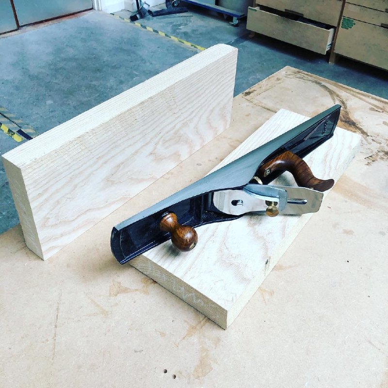
Since Graeme taught me how to setup a plane properly this is a lot easier. However, it also means I realise how quickly a blade can blunt and need honing again, On my todo for next week is get trained on the Tormek blade sharpening machine at Makespace, as the primary bevel at 25˚ has gone on this blade, so I can’t just do the usual 30˚ micro-honing on it, and putting back a primary bevel by hand is a very slow process (I’ve done it once before, and would rather not do so again if I could avoid it).
I also did some more tweaking to the design of the “living hinge” for my effect pedal design (that’s the fancy name for the series of slits you laser cut into the wood to make it bend). One thing that was not quite right, and thus left me wanting to improve it, was that because of the expansion that occurs in the hinge slits as it curves, the top surface of the pedal had a bit of slack in it making it have a slight wiggle if you pulled at the controls. To try and prevent this I played around with the laser-cutter targeted vector DXF file I generated from Fusion 360 in Adobe Illustrator to take away bits at either end of the wooden part to make the top surface be pulled tighter against the 3D printed chassis.
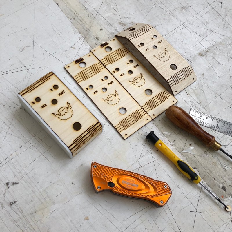
In the above picture the one fitted to the chassis is just about perfect and fits snuggly; it took me a few goes at fiddling to get it just so. It turns out that what I should have done, rather than editing the generated DXF file, was fiddled in Fusion 360 with the settings for the sheet metal model. You can apparently adjust the expected material expansion for a curve, which is really what I should be adjusting, but my method was just quicker to bodge for a one off, but next time I’ll try that.
Another thing I was interested to try was seeing how well I could stain the wood inside a laser cut line without the stain crossing over the cut. I use water based stains and they’ll quite happily chase along the wood grain around the area you actually apply the stain itself. However, it seems that my cuts are deep enough to stop that happening:
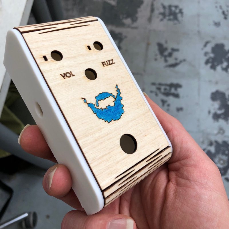
This is probably because I make sure that my laser cut lines, like those around the beard logo here, go about 50% of the way through the material as I know I’ll want to sand the surface after cutting to remove the residue from cutting, and if the lines weren’t cut deep enough they’d just sand out. I do this by testing a box outline that goes over the edge of my test material when calibrating laser powers before cutting (if you’ve never used a laser cutter, at least in a shared space like Makespace, you can’t assume the power settings you used last time work next time as the lenses will be in a different state of cleanliness, thus you always need to calibrate how much power is required to cut/etch every time you use the machine).
Given the CNC Router was out of action, I found myself with an hour or so to spare, and given workshop time is very limited right now I decided to put it to use by working on my soldering, which is improving but could still be better. I had enough components to make a few more fuzz boards, so I just whiled away an hour or so repeating the now familiar circuit, trying to get both more consistent and quicker with my solder joints.
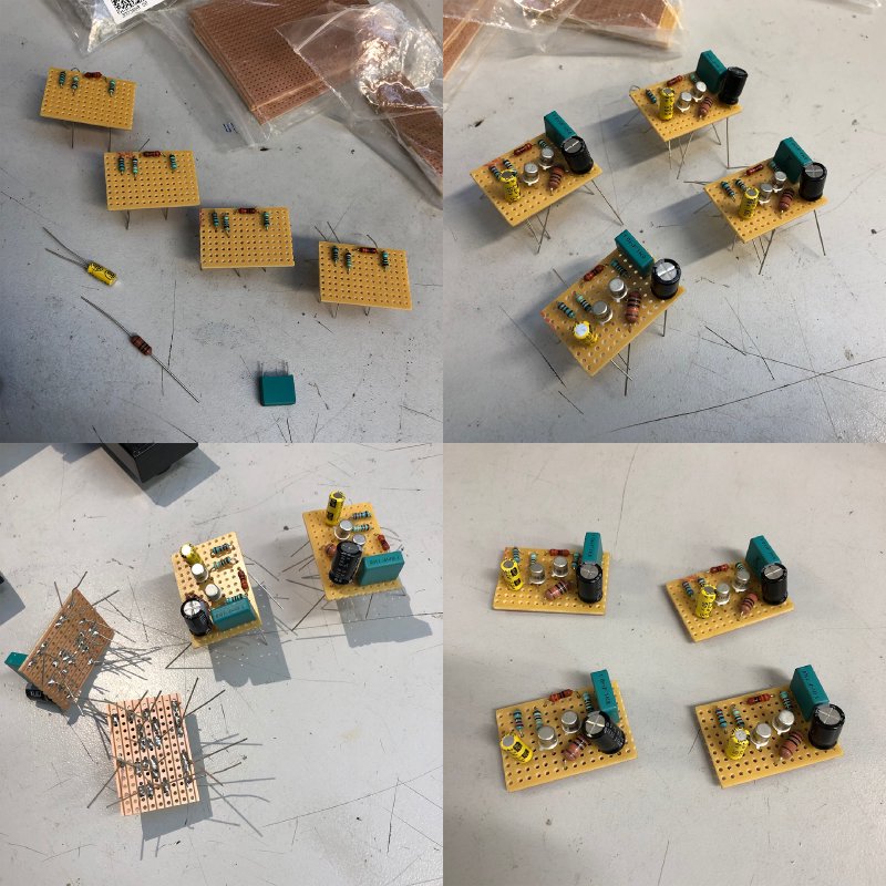
Still not the best, but practice is definitely helping (it got a thumbs up with some critical comments from another Makespace member :).
With all those boards you might think I would be looking to sell some pedals, but no, as to sell electronics requires that you get things certified for safety, which isn’t a cheap process and is hard to justify at small quantities. Even if there’s no active components, as with my pedal board design which just has pass through power, it still counts as a low-voltage electronics device, and so will cost around £3000 to get certified, so my plans to make a small run of those is on hold for now, as it just makes no economic sense to build small numbers of such units when just getting things certified is so expensive.
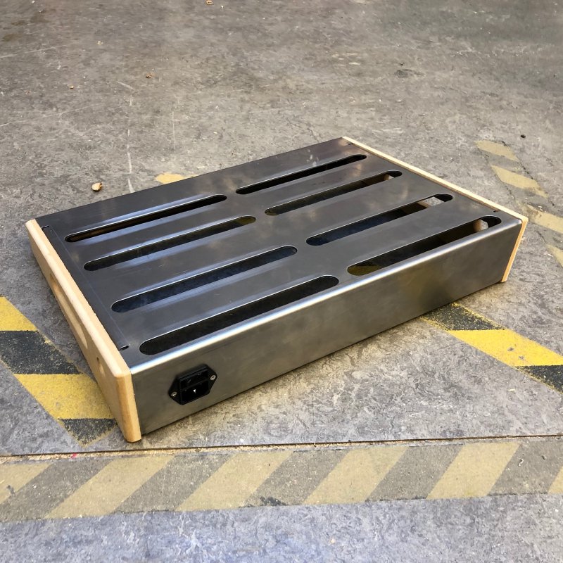
For the pedal board I could just remove the power lead that’s built into it, but then it’s no longer the product I had in mind, and not a product I would want to use personally, so it’s currently just dead in the water as far as the v1 pedalboard goes. I’ve learned a lot from it, and I had plans for a v2 which had some extra features, so now I have to go back to the spreadsheets and try and work out whether I could do something at all sensible in that space economically, without compromising on my vision feature wise, and without having to become a bulk manufacturer.
I’ll try write up some more details on all this in a post shortly, as I think it’s an important missing part of the maker story that everyone seems to ignore for the most part.
Makespace’s 6th birthday party was this week, and as per last year I set up a little mode stall to show things I’d made there. It was a nice moment to reflect on all the different things I’ve made in the last year or so, as I was able to show off a guitar, an amp, a pedal, and a pedalboard all designed and built by me. I just need to start making cables myself, and then I’ll have the lot :)
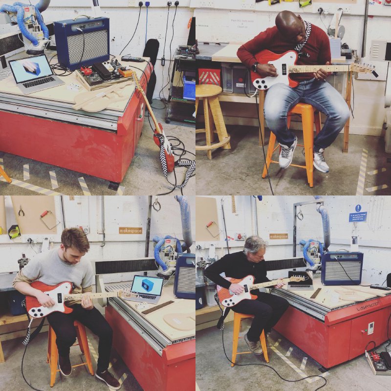
As ever it’s such a kick to hear others make nice sounds with the things I’ve built, so thanks to everyone who came along and had a play. It was also nice to meet a couple of people again from the Autodesk office in Cambridge and show them how I made things and let them see their product being used on a variety of different physical things.
There was also a guitar show down in Newmarket at the end to the week, and I headed down to that to see what was going on. I’ve generally stopped going to guitar shows at the moment, as there’s nothing I particularly need from them, and I’m not in a position yet to exhibit anything; however, given Newmarket is just ten miles down the road it would have been silly not to.
It was nice to catch up with some friends who had stalls there and play some nice guitars and pedals, but made me realise I probably need to make a series of guitars to have people play of different types if I want to start getting into this scene, and here I am struggling to make more than two or three a year at the moment.